
GPS-3065A
GPS-3065A 6½ Digit Bench Multimeter
35 ppm DC voltage · 2500 readings a second · colour display · RS-232, LAN and USB
A 6½ digit bench meter whose screen explains the number: two parameters from one input, and a trend, histogram or history drawn on the instrument rather than on a laptop beside it.
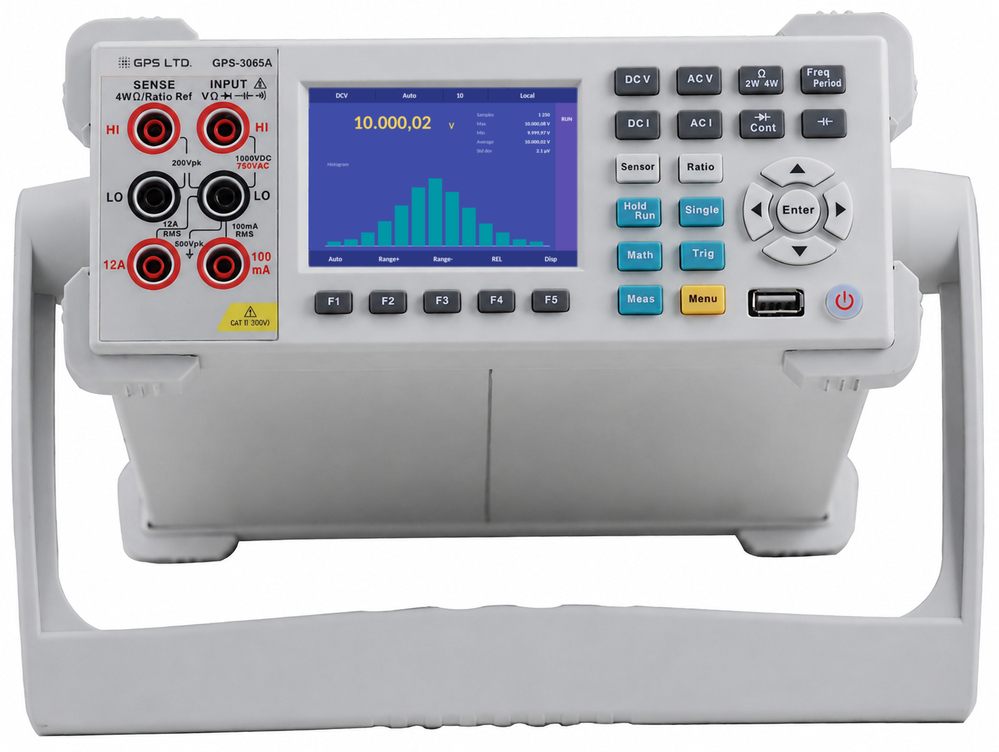
Every function, every range, one screen
Twelve functions, one table. Scan down for the function, across for the range; the figure in the accuracy column is the one-year figure on the range a bench meter lives on.
| Function | Lowest | Highest | Best resolution | Basic accuracy | Notes |
|---|---|---|---|---|---|
| DC voltage | 100 mV | 1000 V | 100 nV | 35 + 5 ppm | Five ranges · 10 MΩ or above 10 GΩ input to 10 V |
| AC voltage | 100 mV | 750 V | 100 nV | 0.06% + 0.03% | True RMS · 3 Hz to 300 kHz · three filters |
| DC current | 10 µA | 12 A | 10 pA | 0.05% + 0.006% | Seven ranges · 100 mA and 12 A terminals, both fused |
| AC current | 100 µA | 12 A | 100 pA | 0.10% + 0.04% | True RMS · 3 Hz to 10 kHz |
| Resistance | 10 Ω | 1 GΩ | 10 µΩ | 100 + 10 ppm | Nine ranges · two-wire or four-wire |
| Frequency | 3 Hz | 300 kHz | 1 µHz | 100 ppm | On 100 mV to 750 V · gate 1 s, 100 ms or 10 ms |
| Period | 3.3 µs | 0.33 s | — | 100 ppm | Same input as frequency |
| Capacitance | 1 nF | 100 mF | 1 pF | 1% + 0.3% | Nine ranges · about two readings a second |
| Temperature | −200 °C | 660 °C | 0.001 °C | ±0.16 °C | Pt100 and Pt1000 preset · user-defined RTD · plus the probe |
| Diode | — | 3 V | 10 µV | — | 1 mA test current |
| Continuity | 1 Ω | 1000 Ω | 0.1 Ω | — | Beeper threshold set anywhere in the range · 10 Ω default |
| DC:DC ratio | 100 mV | 1000 V | — | — | Input over a 100 mV to 10 V reference on the sense terminals |
Accuracy is specified for one year after calibration, at 23 ±5 °C after an hour of warm-up, at 100 PLC with auto-zero on, as ±(ppm or % of reading + ppm or % of range). The figures above are for the 10 V, 1 A and 10 kΩ ranges and the 10 Hz to 20 kHz band; every range and band, the 24-hour and 90-day figures and the temperature coefficients are in the operating manual.
What the screen shows
Three views on the Disp key, all drawn on the instrument. Each keeps the live reading; what changes is what is shown around it.
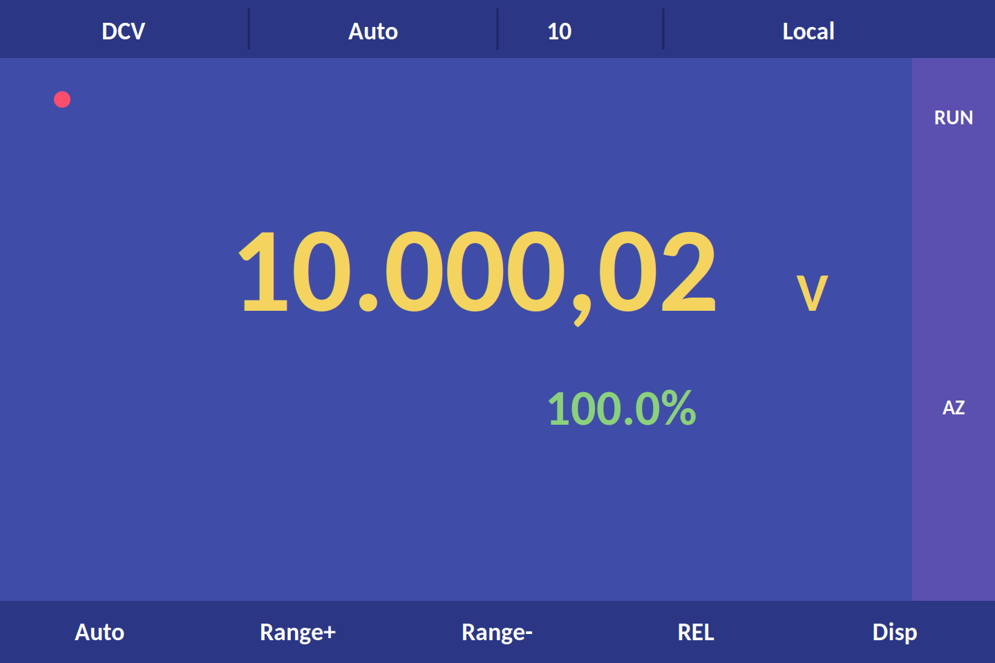
Reading
The main reading with a second parameter from the same input: frequency on AC functions, proportion of range on DC, both voltages on ratio. The status bar carries function, ranging, integration and Local or Remote.
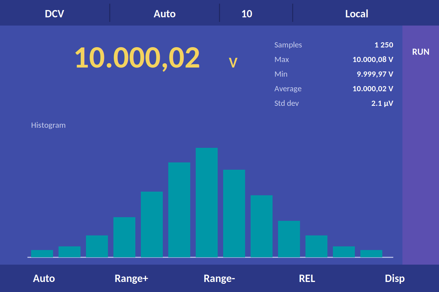
Statistics
Sample count, maximum, minimum, average and standard deviation since the last reset, over a histogram of the readings. Where a source sits, and how much it wanders, at a glance.
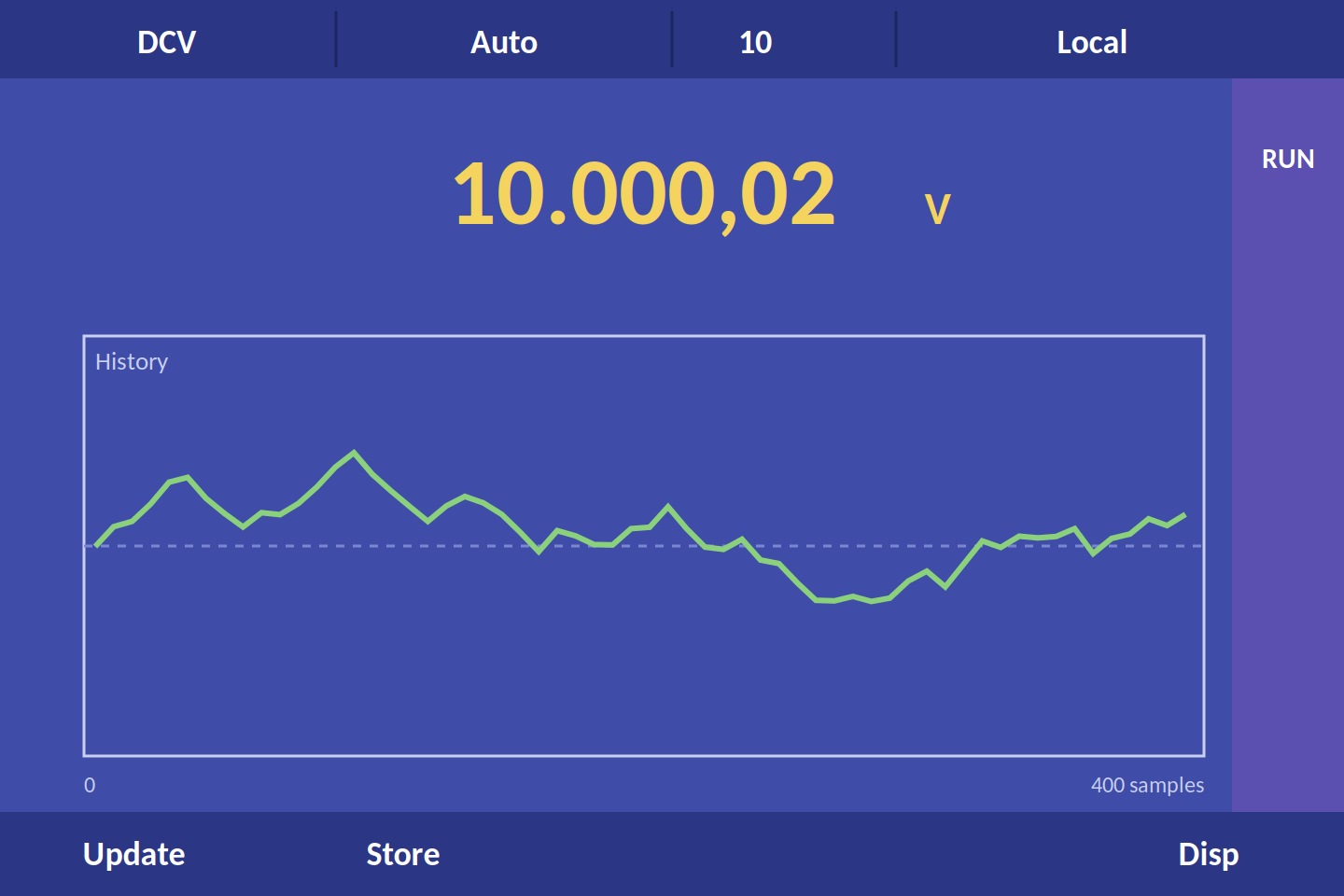
History
The recorded readings as a trend against sample number, kept on the instrument until the function changes. Store writes them to a USB stick as CSV.
Speed or digits
Integration time is the one setting that decides both. Whole power line cycles cancel mains pickup; fractions of a cycle buy speed.
| Resolution | Integration | Time at 50 Hz | Readings a second |
|---|---|---|---|
| 4½, fast | 0.02 PLC | 0.4 ms | 2500 |
| 4½, slow | 0.1 PLC | 2 ms | 500 |
| 5½, fast | 0.2 PLC | 4 ms | 250 |
| 5½, slow | 1 PLC | 20 ms | 50 |
| 6½, fast | 2 PLC | 40 ms | 25 |
| 6½, medium (default) | 10 PLC | 200 ms | 5 |
| 6½, slow | 100 PLC | 2 s | 0.5 |
Auto-zero
A zero reading after each measurement, subtracted before display, removes the instrument’s own offset at the cost of half the reading rate. On by default; off when speed matters more than the last few counts.
Above 10 GΩ input
On the 100 mV to 10 V ranges the input impedance switches from 10 MΩ to greater than 10 GΩ, so a 100 kΩ source loads by 0.001% rather than 1%.
Three AC filters
3 Hz, 20 Hz or 200 Hz lower limits, settling in 7 s, 1 s or 0.1 s. Pick the fastest whose limit is below the lowest frequency you will measure.
Into the test system
A bench meter earns its place in a rack by how little work it takes to talk to, and by what it can do without being talked to at all.
Remote control
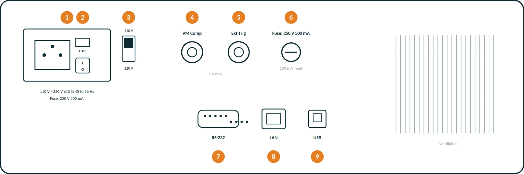
RS-232 to 256,000 baud, LAN and USB, with an SCPI command set that can be switched between the 34401A, the 34410A and the Fluke 45, so the test code written for those meters runs here. Interface settings are kept through a power cycle. The commands are in the separate programming guide.
Trigger handshake
Auto, single or external trigger, 1 to 50,000 samples per trigger and a delay of up to an hour between them. A negative pulse on Ext Trig starts a measurement and VM Comp reports it done, which is the handshake a scanner or switch unit expects.
Limit test and logging
Upper and lower limits on any function, pass and fail on the screen, the beeper, and as pulses on the rear connector. Readings are kept on the instrument and written to a USB stick as CSV, and calibration needs only a 10 V and a 10 kΩ standard.
Where it is used
Calibration laboratories
Class figures with a 90-day and a 24-hour tier, two-standard calibration, and a certificate at order.
Automated test
SCPI over LAN or USB with the 34401A command set, trigger handshake with a scanner, 50,000 readings per trigger.
Design characterisation
Statistics, histogram and trend on the instrument while a prototype warms up or drifts.
Production test
Limit test with pass and fail on the rear connector, fixed range and 4½ digits for 2500 readings a second.
Incoming inspection
Four-wire resistance to 10 µΩ, capacitance to 100 mF, RTD temperature, one instrument on the bench.
Teaching benches
A colour screen that shows what integration, filtering and auto-zero do to a reading, in front of the student.
Technical specifications
Everything that is not a range. Ranges and accuracies are in the matrix above; the full per-range tables are in the operating manual.
| Specification | GPS-3065A |
|---|---|
| Display | 3.5 inch colour TFT, 480 × 320 · two parameters from one input · reading, statistics and history views |
| Reading rate | Up to 2500 readings a second at 4½ digits · integration 0.02 to 100 PLC · auto-zero, on by default |
| Ranging | Automatic or manual on every function · 120% over-range except on 1000 V, 750 V and 12 A |
| DC input | 10 MΩ, or greater than 10 GΩ on the 100 mV to 10 V ranges · common-mode rejection 140 dB · normal-mode 60 dB at 1 PLC and above |
| AC input | 1 MΩ with less than 100 pF · AC coupled true RMS · crest factor to 5 · filters 3 Hz, 20 Hz and 200 Hz |
| Maths | Relative · max, min, average, standard deviation · dB and dBm with a 2 to 8000 Ω reference · limit test with pass and fail outputs |
| Triggering | Auto, single or external · 1 to 50,000 samples per trigger · delay 0 to 3600 s · VM Comp output · reading hold with 0.01 to 10% sensitivity |
| Data | Reading history on the instrument · CSV logging to USB memory · firmware update from USB |
| Interfaces | RS-232 to 256,000 baud · LAN · USB device · USB host · Ext Trig in and VM Comp out on BNC |
| Programming | SCPI · command sets compatible with the 34401A and 34410A and the Fluke 45 |
| Input protection | CAT II 300 V · 1000 V peak HI to LO · 500 V peak LO to earth · 200 V peak SENSE · 15 A internal and 500 mA rear fuse · 2500 V peak transient |
| Calibration | Two-standard calibration from a 10 V and a 10 kΩ reference · 24-hour, 90-day and one-year figures |
| Power | 110 V or 220 V ±10% on the rear selector · 45 to 66 Hz · under 20 W |
| Environment | Operating −5 to 45 °C, 5 to 85% RH · storage −20 to 70 °C |
| Size and weight | 265 × 105 × 335 mm · about 2.7 kg |
| Order code | 423065 |
What’s in the box
- GPS-3065A bench multimeter
- Test lead set with 2 mm probes
- Crocodile clips
- Mains lead and two spare fuses
- Operating manual and calibration certificate
Before you order
Inputs are on the front panel only and there is no IEEE-488 port on this model; remote control is RS-232, LAN or USB. Set the rear voltage selector to 110 V or 220 V before connecting. Optional: rack mounting kit, Pt100 probe, RS-232 and USB cables, and the programming guide with the SCPI command set. Traceable calibration is available at order.