
GPS-290PR
GPS-290PR Three-Phase Power Clamp Meter
Rooted in a flexible coil · 6000 A · 3600 kW
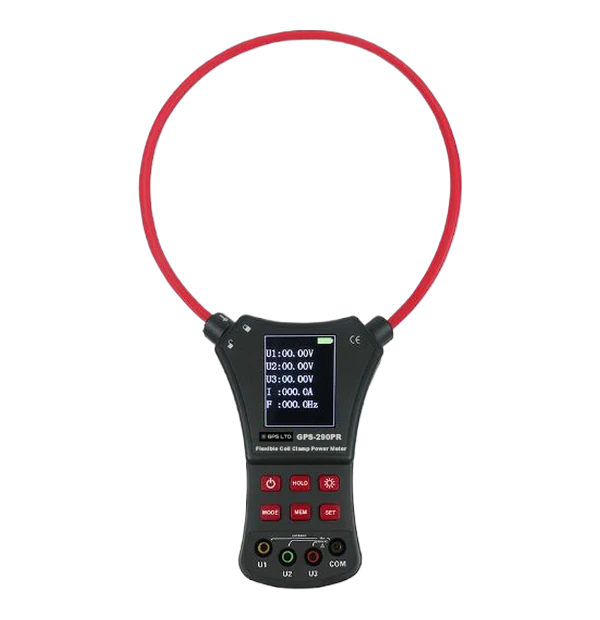
A three-phase power meter on the end of a Rogowski coil. The loop is flexible, has no iron core and no exposed metal, so it goes round a busbar or a cable bundle that a rigid jaw cannot reach, and reads voltage, current, power, power factor and phase sequence together on one screen.
- Rogowski coil, φ200 mm
- Three-phase
- kW, kVA, kvar, kWh, PF
- 200-group memory, USB
Why a Rogowski coil
A conventional clamp needs an iron core, which limits how big the opening can be and saturates on high current. A Rogowski loop has neither problem, and it bends.
A coil, not a jaw
A flexible Rogowski loop with no exposed metal wraps round a busbar, a cable bundle or a conductor at the back of a crowded cabinet, where a rigid jaw will not reach. Double-wrap it when the current is small.
Nothing to saturate
No iron core means no magnetic saturation and phase error close to zero. Response stays linear all the way to 6000 A, and the coil copes with the distorted waveforms around drives, thyristors and welding sets.
Three-phase, one screen
Three voltages, current, active, reactive and apparent power, power factor, frequency, phase angles and phase sequence, read together on a 2.8-inch colour display.
6000 A and 3600 kW
Current from 0.0 A to 6000 A and power to 3600 kW, with fully automatic ranging so resolution steps with the reading.
200 readings to USB
Store 200 groups on the meter and upload them over USB with the supplied software for reading, saving and printing.
Built for the field
Backlit colour LCD, data hold, over-range indication, low battery warning and auto power off after 15 minutes. Runs on four AAA cells.
Technical specifications
| Range | Condition | Accuracy |
|---|---|---|
| AC voltage | ||
| 0.00 V to 60.00 V | ±0.5% FS | 0.01 V |
| 60.0 V to 600.0 V | ±0.5% FS | 0.1 V |
| AC current · via the Rogowski coil | ||
| 0.0 A to 600.0 A | ±0.5% FS | 0.1 A |
| 600 A to 6000 A | ±0.5% FS | 1 A |
| Active power (W), apparent power (VA) and reactive power (var) · the same six ranges apply to each, in its own unit | ||
| 0.00 to 36.00 | ±1% FS | 0.01 |
| 36.0 to 360.0 | ±1% FS | 0.1 |
| 360 to 3600 | ±1% FS | 1 |
| 3.60 k to 36.00 k | ±1% FS | 0.01 k |
| 36.00 k to 360.0 k | ±1% FS | 0.1 k |
| 360 k to 3600 k | ±1% FS | 1 k |
| Electric energy | ||
| 0.00 Wh to 36.00 Wh | ±1% FS | 0.01 Wh |
| 36.0 Wh to 360.0 Wh | ±1% FS | 0.1 Wh |
| 360 Wh to 3600 Wh | ±1% FS | 1 Wh |
| 3.60 kWh to 36.00 kWh | ±1% FS | 0.01 kWh |
| 36.00 kWh to 360.0 kWh | ±1% FS | 0.1 kWh |
| 360 kWh to 360000 kWh | ±1% FS | 1 kWh |
| Frequency, power factor and phase angle | ||
| Frequency · 25.0 Hz to 600.0 Hz | ±0.5 Hz | 0.1 Hz |
| Power factor · 0.300 to 1.000 | ±0.5% FS | 0.001 |
| Phase angle · 0° to 360° | ±0.5° | 0.1° |
| Phase angle accuracy by current · the ±0.5° figure applies only above 60 A | ||
| 5.0 A to 20.0 A | ±4° | 0.1° |
| 20.0 A to 40.0 A | ±2° | 0.1° |
| 40.0 A to 60.0 A | ±1° | 0.1° |
| Above 60.0 A | ±0.5° | 0.1° |
| General | ||
| Display | — | 2.8-inch TFT colour LCD, 58 × 44 mm · backlit |
| Current sensor | — | Rogowski flexible coil, φ200 mm · conductor centred in the loop |
| Ranging · sampling | — | Fully automatic · 2 readings per second · 50/60 Hz auto recognition |
| Line voltage | — | For measurement on circuits below 600 V AC |
| Dielectric strength | — | 3700 V AC rms between core and case |
| Data storage | — | 200 groups · USB upload, 1.8 m cable · PC software supplied |
| Power | — | 6 V DC, 4 × LR03 AAA · battery reminder at 4.8 V · auto off after 15 min |
| Environment | — | Operating −10 to 40 °C · below 80% RH |
| Dimensions · weight | — | 200 × 370 × 35 mm · meter 272 g, 755 g complete |
Where it is used
Load surveys and energy audits
Record kW and kWh across a site to find where the consumption actually goes.
Phase balancing
Compare the three phases and check power factor to cut losses on a distribution board.
Busbars and dense cable runs
Where a rigid jaw cannot be threaded in and the conductor cannot be disconnected.
Drives and distorted supplies
Thyristors, variable-speed drives and welding sets, where CT clamps struggle.
Commercial and industrial HVAC
Compressor and plant loads, with running power and power factor together.
What’s in the box
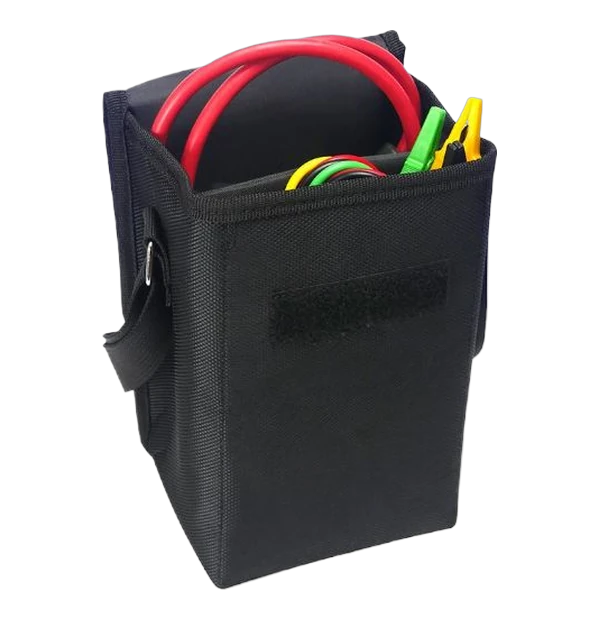
- GPS-290PR power clamp meter with Rogowski coil
- Test leads, four: yellow, green, red and black
- USB communication cable
- PC software on CD
- Meter bag
Supplied with the φ200 mm coil. Other coil diameters can be made to order for larger busbars.
Before you order
This is an AC-only three-phase power meter, not a general-purpose multimeter: there is no DC, resistance, continuity or diode function. Measurement is on circuits below 600 V AC. Phase angle accuracy depends on current, ±4° between 5 and 20 A tightening to ±0.5° above 60 A, so read phase and power factor on a loaded circuit. The conductor should sit at the centre of the loop.
Compliance and downloads
Safety and approvals
- Line voltage
- For measurement on circuits below 600 V AC
- Dielectric strength
- 3700 V AC rms between core and case
- CAT rating
- Not published by the manufacturer; contact us before use on a higher-energy supply
- Warranty
- 1 year, subject to product registration with GPS LTD
- Calibration
- Service and calibration available; ask us to quote with the instrument