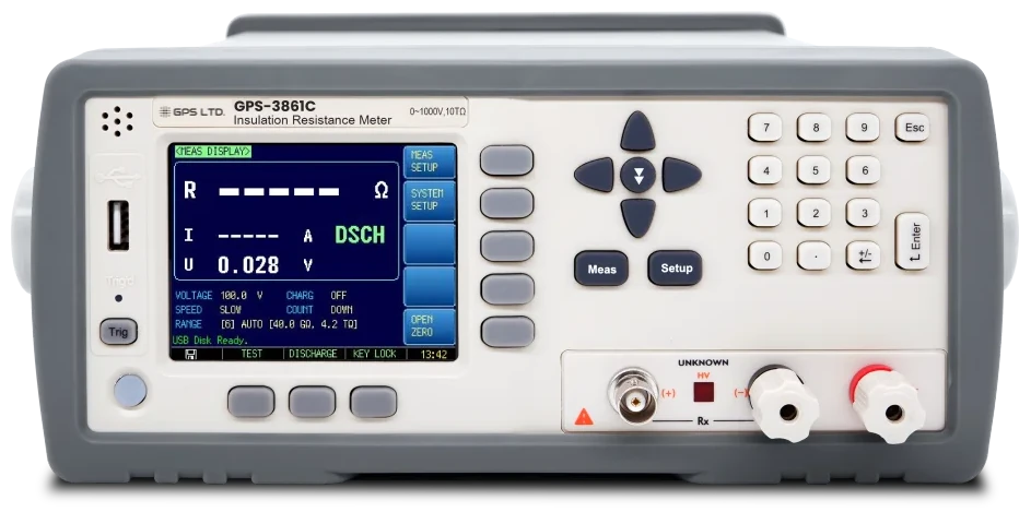
GPS-3861C
GPS-3861C Insulation Resistance Meter
1.0 to 1000 V DC · 100 kΩ to 10 TΩ · up to 55 readings/s
Insulation is judged at the voltage it has to stand, so the GPS-3861C lets you choose that voltage to a tenth of a volt anywhere from 1 V to 1000 V, then reads the resistance and the leakage current side by side. From a capacitor on a sorting line to a reel of cable on the bench.
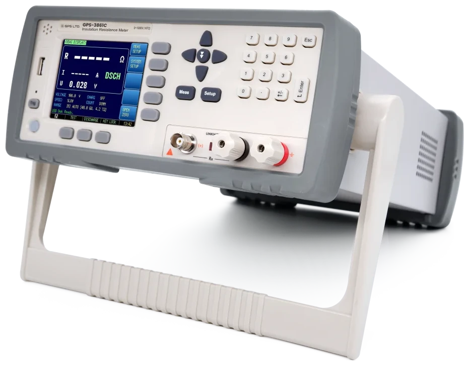
Three things that make a high resistance reading mean something
At gigaohms and teraohms the instrument is reading picoamps, and the way the test is set up matters as much as the meter. All three of these are under your control.
The voltage you test at
Pick one of the common voltages from a soft key, 50, 100, 250, 500 or 1000 V, or type any value in 0.1 V steps. The six ranges move with it: at 100 V the meter reads 1 MΩ to 1 TΩ, and at 1000 V the top range reaches 10 TΩ.
- 1.0 to 1000 V DC
- ±1% above 10 V · negative output
The time you give it
A cable or a capacitor draws charging current before it settles, and a reading taken too early is low. The charge timer holds the voltage on for up to 999.9 s before the reading is taken, and the contact check catches a capacitive part that is not actually connected.
- Charge timer to 999.9 s
- ±0.5% · counts up or down
The current you keep out
Surface leakage across a dirty or damp insulator flows in parallel with the resistance you want. Taking the shield or guard to the ground terminal steers that current around the measurement, and an open circuit zero stored for every range removes the leads’ own contribution.
- Guard terminal
- Open circuit zero across all ranges in one go
Accuracy at the slow rate: ±5% below 1 MΩ, ±1% above 1 MΩ, ±3% above 1 GΩ, ±5% above 10 GΩ and ±10% above 1 TΩ, at 23 °C ±5 °C and 65% relative humidity, after an open circuit zero and more than 60 minutes warm-up.
Charge, test, discharge
Every measurement runs the same three states, and the instrument shows which one it is in. That is what makes a high-voltage test safe to repeat a hundred times.
1 · Charge
The test voltage goes on and the charge timer starts. Skip it with the charge time at zero, or press TEST to go straight to the reading.
2 · Test
Resistance, leakage current and the voltage at the terminals are read together, with the sorting result when the comparator is on.
3 · Discharge
The voltage comes off and the part is discharged quickly through the instrument. With automatic discharge on, this follows every reading by itself.
The device under test is connected and removed only in the discharge state. Polarised parts such as electrolytic capacitors go positive to (+) and negative to (−).
The range follows the voltage
Six ranges, chosen automatically, held, or set from the comparator limit, cover a span that slides upwards as the test voltage rises. These are the spans at eleven typical voltages.
| Voltage | Range 1 | Range 2 | Range 3 | Range 4 | Range 5 | Range 6 |
|---|---|---|---|---|---|---|
| 1 V | Not specified | 1M – 10M | 10M – 100M | 100M – 1G | 1G – 10G | 10G – 100G |
| 10 V | 100k – 1M | 1M – 10M | 10M – 100M | 100M – 1G | 1G – 10G | 10G – 100G |
| 25 V | 250k – 2.5M | 2.5M – 25M | 25M – 250M | 250M – 2.5G | 2.5G – 25G | 25G – 250G |
| 50 V | 500k – 5M | 5M – 50M | 50M – 500M | 500M – 5G | 5G – 50G | 50G – 500G |
| 75 V | 750k – 7.5M | 7.5M – 75M | 75M – 750M | 750M – 7.5G | 7.5G – 75G | 75G – 750G |
| 100 V | 1M – 10M | 10M – 100M | 100M – 1G | 1G – 10G | 10G – 100G | 100G – 1T |
| 125 V | 2.5M – 12.5M | 12.5M – 125M | 125M – 1.25G | 1.25G – 12.5G | 12.5G – 125G | 125G – 1.25T |
| 250 V | 5M – 25M | 25M – 250M | 250M – 2.5G | 2.5G – 25G | 25G – 250G | 250G – 2.5T |
| 500 V | 10M – 50M | 50M – 500M | 500M – 5G | 5G – 50G | 50G – 500G | 500G – 5T |
| 750 V | 10M – 75M | 75M – 750M | 750M – 7.5G | 7.5G – 75G | 75G – 750G | 750G – 7.5T |
| 1000 V | 10M – 100M | 100M – 1G | 1G – 10G | 10G – 100G | 100G – 1T | 1T – 10T |
Units are ohms: k = 10³, M = 10⁶, G = 10⁹, T = 10¹². The lowest range is not specified at 1 V. For leakage current measurements a held range is recommended.
On the bench and on the line
Slow for the bench, fast for a machine. The same instrument does both, and the sorting decision goes straight to the PLC.
PASS, UPPER or LOWER
- Set a lower limit, and an upper one if you need it. The upper limit can be turned off.
- Choose the rate: about 3 readings a second for the best accuracy, 25 or 55 for automatic testing.
- The beeper sounds on the good result, on the bad one, or not at all, and the nominal range mode picks the fastest range from the lower limit.
Optocoupler isolated, on your supply
The Handler outputs pass, fail, open circuit and end of test, with a pair of relay contacts for the sorting result, and takes trigger, charge, discharge and keypad lock inputs. Everything is optocoupler isolated and runs from your own 3.3 to 24 V DC supply. The charge and discharge inputs will also take a foot switch.
RS-232 carries a full SCPI command set at up to 115200 baud, with results sent on request or automatically after every test. Readings can also be logged straight to a USB flash drive as CSV files, on a timer, on every trigger or at the press of a key.
Technical specifications
| Measures | Insulation resistance and leakage current, shown with the test voltage |
|---|---|
| Resistance range | 100 kΩ to 10 TΩ across six ranges · maximum reading 9999 |
| Accuracy | ±5% below 1 MΩ · ±1% above 1 MΩ · ±3% above 1 GΩ · ±5% above 10 GΩ · ±10% above 1 TΩ |
| Test voltage | −1.0 to −1000 V DC in 0.1 V steps · accuracy ±10% below 10 V, ±1% above · maximum charging current 30 mA ±5 mA |
| Measurement rate | Slow about 3, medium about 25, fast about 55 readings per second |
| Ranging | Auto, hold, or nominal from the comparator lower limit |
| Charge timer | 0 to 999.9 s · accuracy ±0.5% · counts up or down · automatic discharge on or off |
| Correction | Open circuit zero for all ranges in one operation · contact check for capacitive parts above 100 pF |
| Comparator | PASS, UPPER and LOWER · beeper off, on good or on fail |
| Trigger | Internal, manual, external on a rising or falling edge, or bus · delay 1 ms to 60 s |
| Display | 3.5 in true-colour TFT · English interface · keypad lock |
| Interfaces | RS-232 with SCPI, 1200 to 115200 baud · Handler · USB flash drive, CSV logging · RS485 and USB-to-RS-232 optional |
| Handler | Pass, fail, open circuit and end of test outputs · relay contacts · trigger, charge, discharge and keypad lock inputs · optocoupler isolated · external 3.3 to 24 V DC supply |
| Access | Administrator and user accounts with an optional password |
| Power | 198 to 242 V AC · 50/60 Hz · 30 VA maximum · 250 V 1 A slow-blow fuse |
| Environment | Operating 10 to 40 °C, 10% to 80% RH · storage 0 to 50 °C, 10% to 90% RH |
| Dimensions · weight | 264 × 107 × 350 mm (W × H × D) · about 5 kg |
Before you order
Worth knowing
- The test voltage is a negative output on the (−) terminal. Polarised parts must be connected the right way round.
- The figures above hold at the slow rate. The medium and fast rates are for automatic sorting.
- The Handler needs your own 3.3 to 24 V DC supply and works in external trigger mode. Without a supply, only its relay contacts are active.
- Mains input is 198 to 242 V AC. There is no 110 V setting.
Options
RS485 and USB-to-RS-232 interfaces are available to order. Tell us in your enquiry if you need either, or if you would like the instrument supplied with a UKAS calibration certificate.
What’s in the box
- GPS-3861C meter
- Test cable
- RS-232 communication cable
- Power cord
- Spare 1 A slow-blow fuse
- Operating manual and calibration certificate