
GPS-3200 series
GPS-3200 Series Precision Benchtop LCR Meters
10 Hz to 1 MHz, continuous · ±0.05% basic · six and a half digits
A component behaves differently at every frequency, and a bench bridge is what lets you go and look. The frequency is continuous rather than a short list, the drive is held where you set it, and a bias can be put across the part while you measure. Five models, separated only by how far up they reach.
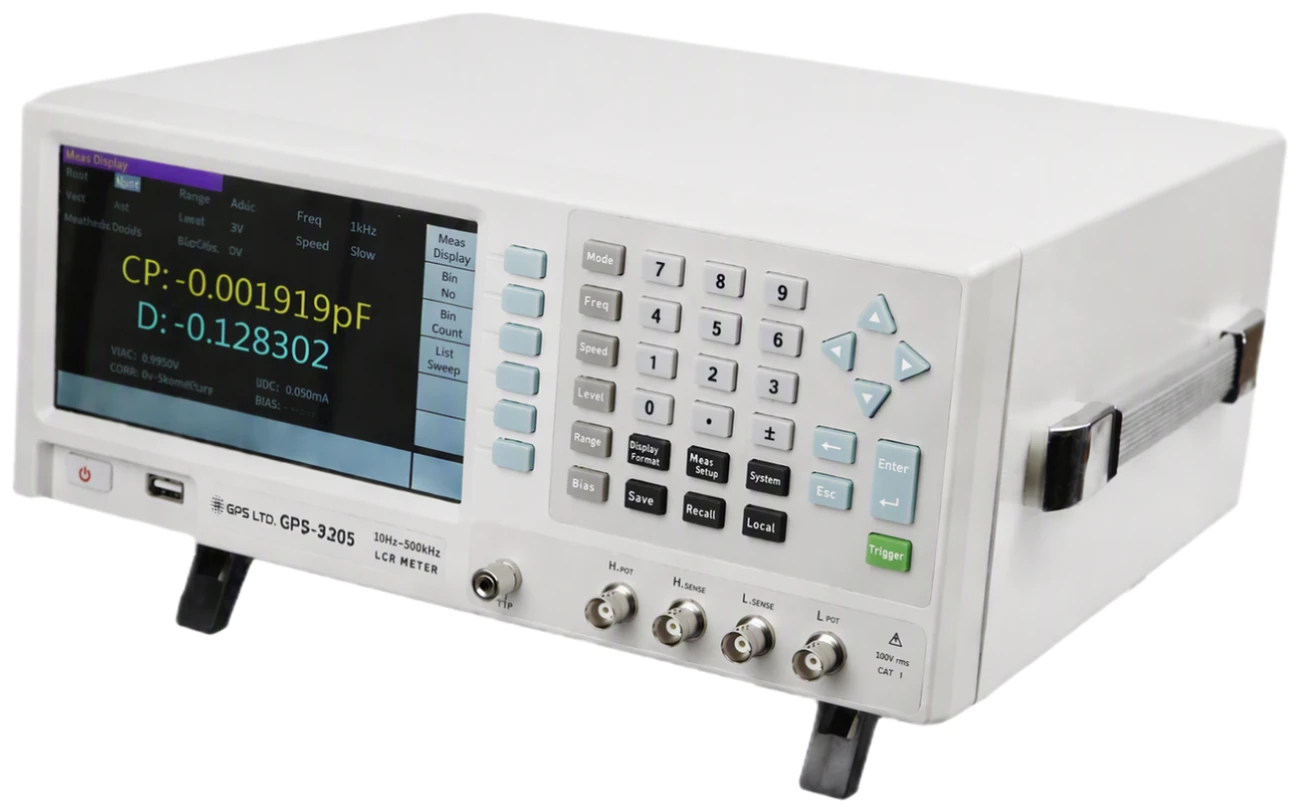
Three things you cannot do with a handheld
A handheld tells you what a part measures. A bench bridge lets you decide the conditions first, which is the whole of component characterisation.
Frequency you choose, not frequency you are given
Continuously adjustable from 10 Hz in steps of 1 mHz, up to 1 MHz on the top model. A handheld gives you five or six fixed points. This gives you the one the part will actually see, and a ten-point sweep to find where it stops behaving.
- 10 Hz to 1 MHz
- Resolution 1 mHz, accuracy ±0.01%
A drive that stays where you put it
Set the level as a voltage from 10 mV to 2 V or as a current from 100 µA to 20 mA, and automatic level control holds it there as the load changes. Source impedance is selectable, which is what makes an inductor reading comparable with a figure taken on another instrument.
- 30 Ω or 100 Ω source
- Level control to ±(2% + 2 mV)
Bias, for the parts that need it
Electrolytics and varactors do not behave the same way with a working voltage across them as they do at zero. Bias runs to ±2 V and ±20 mA from inside the instrument, and to ±60 V from an external supply at the rear.
- ±2 V and ±20 mA internal
- To ±60 V from an external supply
Nine impedance ranges from 30 Ω to 300 kΩ sit under all of it, automatic or held, and holding the range is what speeds a long batch up.
Five models, one instrument
Everything below is common to all five. What separates them is the top of the frequency range, and the two smaller ones differ in a couple of details worth knowing before you order.
| Model | Frequency range | Fast measurement | GPIB | Order code |
|---|---|---|---|---|
| GPS-3201 | 10 Hz to 100 kHz | 20 readings/s | Optional | 503201 |
| GPS-3202 | 10 Hz to 200 kHz | 50 readings/s | Fitted | 503202 |
| GPS-3203 | 10 Hz to 300 kHz | 50 readings/s | Fitted | 503203 |
| GPS-3205 | 10 Hz to 500 kHz | 50 readings/s | Fitted | 503205 |
| GPS-3210 | 10 Hz to 1 MHz | 50 readings/s | Fitted | 503210 |
The lead-type Kelvin fixture is supplied with the GPS-3203, 3205 and 3210. All five come with the four-terminal Kelvin cable and the short circuit bar.
Measurement display range
Two parameters are taken in the same cycle, in any of twenty pairings, and either can be left for the instrument to choose.
| Parameter | Display range | Measured as |
|---|---|---|
| Capacitance | 0.001000 pF to 99.9999 F | Cp or Cs |
| Inductance | 0.001000 nH to 99.9999 kH | Lp or Ls |
| Resistance, reactance and impedance | 0.001000 mΩ to 999.999 MΩ | Rp, Rs, Xs and |Z| |
| Conductance, susceptance and admittance | 0.001000 µS to 999.999 kS | G, B and |Y| |
| Dissipation and quality | ±0.000001 to 9.99999 · ±0.001 to 99999.9 | D and Q |
| Phase angle | ±179.9999° or ±3.14159 rad | θd or θr |
±0.05% is the best case. It applies on the slow or medium rate, between 30 Hz and 10 kHz, from 10 Ω to 100 kΩ, at a drive between 0.5 V and 1.5 V, with correction run and ranging automatic. Outside that the accuracy tables in the datasheet give the figure that applies.
Sorting a reel, not a part
Both of these exist because the instrument is expected to sit on a line rather than a bench, making the same decision thousands of times without anyone reading the screen.
Nine bins, and a count of each
- Set limits as absolute values, as a deviation from a nominal, or as a percentage of it.
- Parts fall into one of nine bins, an out-of-bin, or an auxiliary bin when the main parameter passes and the second one does not.
- Each bin counts to 999999, and the Handler interface drives the machine that does the sorting.
Ten points, one trigger
A sweep runs up to ten points of frequency, drive level or bias, each with its own upper and lower limit. In sequential mode one trigger sweeps the lot and reports at the end; in stepping mode each trigger advances one point. It is the difference between knowing a capacitor is in tolerance at 1 kHz and knowing it is in tolerance across the band it will work in.
Triggering can be internal, from the front panel, from the handler or over the bus, with a delay of up to ten seconds to let a part settle on the contacts before the reading is taken.
Technical specifications
| Measures | Twenty parameter pairings · main from Cp, Cs, Lp, Ls, Rs, |Z|, |Y| and G · second from D, Q, G, B, Rp, Rs, Xs and phase angle in degrees or radians |
|---|---|
| Basic accuracy | ±0.05% · six and a half digit resolution |
| Test frequency | 10 Hz to 1 MHz, model dependent · 1 mHz resolution · ±0.01% accuracy |
| Test level | Voltage 10 mVrms to 2 Vrms at ±(5% + 5 mV) · current 100 µArms to 20 mArms at ±(5% + 50 µA) · automatic level control |
| Source impedance | 30 Ω or 100 Ω, selected on the instrument |
| DC bias | Internal −2 V to +2 V at ±(2% + 5 mV), and −20 mA to +20 mA · external −60 V to +60 V |
| Ranging | Nine impedance ranges, 30 Ω, 100 Ω, 300 Ω, 1 kΩ, 3 kΩ, 10 kΩ, 30 kΩ, 100 kΩ and 300 kΩ · automatic or held |
| Measurement rate | Slow 1.25, medium 10 and fast 50 readings per second · custom from 0.5 to 200 · fast is 20 readings per second on the GPS-3201 |
| Correction | Open, short and load · open and short interpolated across 49 fixed frequency points, or taken at a chosen point · cable length 0, 1, 2 or 4 m · self-calibration |
| Trigger | Internal, manual, external or bus · delay 0 to 10 s in 1 ms steps |
| Display | 7 in TFT, 800 × 480 · English interface · 32 backlight steps · dual parameter reading |
| Interfaces and storage | LAN, RS232, GPIB, USB device, USB host and Handler · ten setups internally and ten on USB · readings as CSV and screens as image files |
| Power and size | 220 V AC ±10%, 45 to 55 Hz, 110 V optional · under 20 W · 330 × 285 × 136 mm · 3.6 kg |
| Environment | Operating 0 to 40 °C · humidity 15% to 85% · altitude to 2000 m · 30 minutes warming, up to 16 hours continuous |
What’s in the box
- GPS-3200 series meter
- Four-terminal Kelvin test cable
- Lead-type Kelvin test fixture, GPS-3203, 3205 and 3210
- Gold-plated short circuit bar
- Three-core power cord
- Instruction manual and warranty certificate
Fixtures and leads
Available separately: GPIB, RS232 and USB leads, 2 m and 4 m test cables, an SMD component fixture, an LCR test pen with a four-wire surface mount fixture, and a Kelvin fixture. Cable length is compensated in the instrument at 0, 1, 2 or 4 m, so a longer lead does not cost you the correction.