
GPS-313XC series
GPS-313XC Series Precision Benchtop LCR Meters
Continuous frequency to 300 kHz · ±0.05% basic · six digits
Four readings at once: a main parameter, a second beside it, and two monitors of your choosing. Frequency and drive are continuous rather than a short list of settings, so the conditions are yours to state rather than yours to accept. Three models, separated by how far up the range reaches.
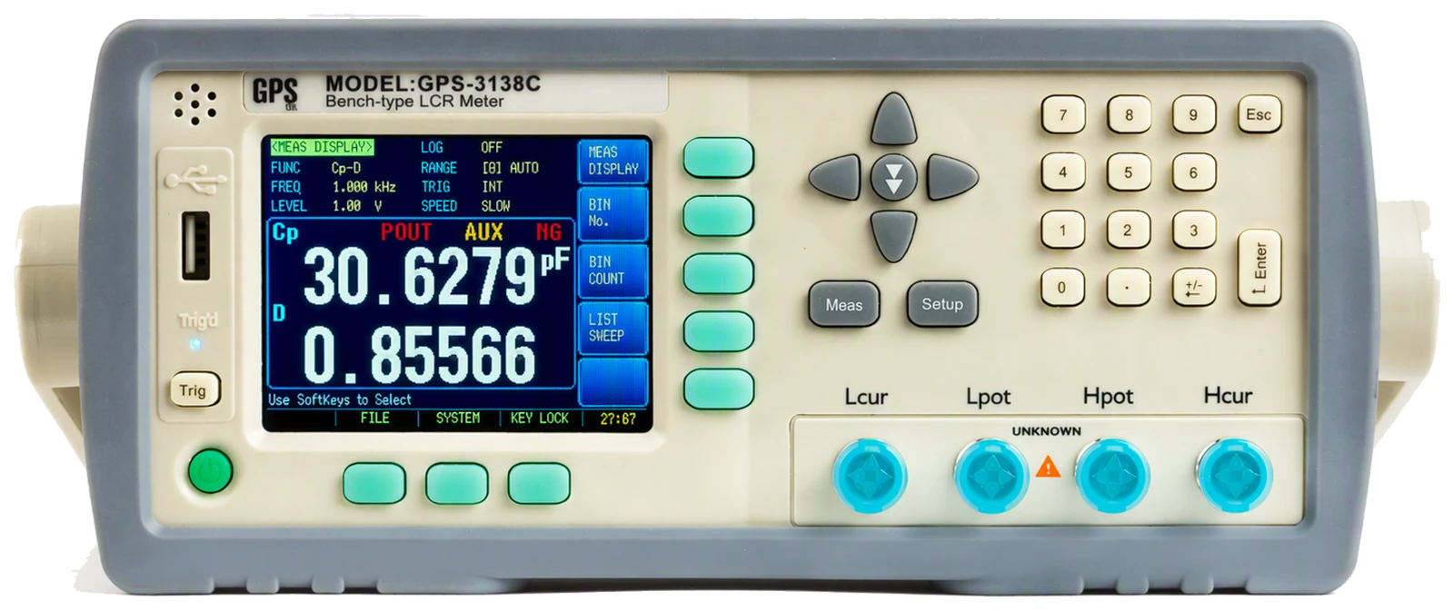
Three things you set, and one you read back
A component has no single value, and a bench bridge earns its place by letting you decide the conditions before it answers. All three settings sit on screen with the reading, and the instrument monitors the drive it actually delivered.
Frequency, continuous and fine
Not a list of points. Anywhere in the range, stepping by 0.0001 Hz at the bottom and holding to ±0.01%. Where the range starts depends on the model: the 300 kHz instrument reaches down to 10 Hz, the other two start at 50 Hz.
- To 100, 200 or 300 kHz
- Floor 50 Hz, or 10 Hz on the GPS-3139C
Drive as a voltage or as a current
10 mV to 2 V, or 100 µA to 20 mA, with automatic level control holding whichever you pick at the part rather than at the generator. Source impedance is selectable at 30 Ω, 50 Ω or 100 Ω, which matters for current-sensitive parts like high-permeability cores.
- 30 Ω, 50 Ω or 100 Ω
- 100 Ω matches the common bench bridges
Bias, and DC resistance
An internal bias of up to ±2.5 V can sit across the part while it is measured, for electrolytics and for cores that behave differently with a working voltage on them. A separate DC resistance mode reads the winding itself, on the same terminals.
- ±2.5 V internal bias
- DCR from 0.00001 Ω to 99.9999 MΩ
Two of the monitor readings can be the drive voltage and current the part actually saw, which is the check worth having when a level-sensitive component is not reading as expected.
Three models, one instrument
Same chassis, same display, same panel. What changes is the top of the frequency range, and on the 300 kHz model the bottom of it as well.
| Model | Frequency range | Typical use | Order code |
|---|---|---|---|
| GPS-3135C | 50 Hz to 100 kHz | General capacitors and inductors | 510150 |
| GPS-3138C | 50 Hz to 200 kHz | Switching supply and EMI components | 510283 |
| GPS-3139C | 10 Hz to 300 kHz | Wideband work, and anything below 50 Hz | 510933 |
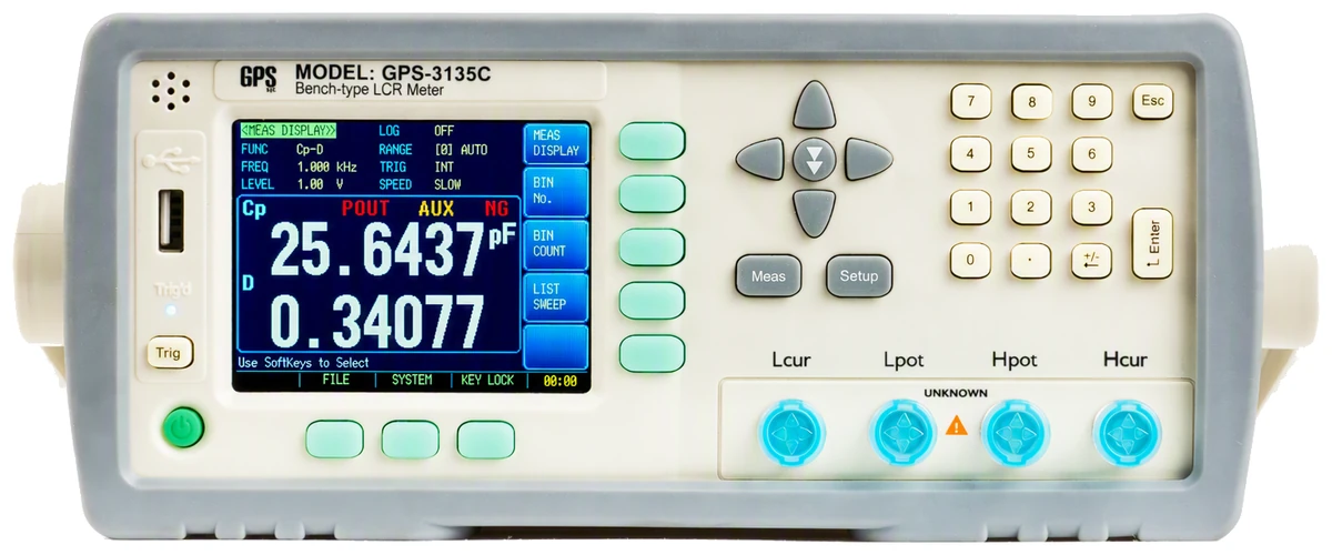
Pick the model that covers your highest test frequency with a little headroom. The one case where the choice is not about the top of the range is low-frequency work: only the GPS-3139C goes below 50 Hz.
Measurement display range
Six digits on the main and the second reading, with two more parameters monitored alongside them without costing any measurement time.
| Parameter | Display range | Measured as |
|---|---|---|
| Inductance | 0.00001 nH to 9999.99 H | Ls or Lp |
| Capacitance | 0.00001 pF to 999.999 mF | Cs or Cp |
| Resistance, reactance and impedance | 0.00001 Ω to 99.9999 MΩ | Rs, Rp, X and |Z| |
| Conductance and susceptance | 0.01 nS to 999.999 S | G and B |
| DC resistance | 0.00001 Ω to 99.9999 MΩ | Separate mode |
| Dissipation and quality | 0.00001 to 9.99999 · 0.00001 to 99999.9 | D and Q |
| Phase angle | ±179.999° or ±3.14159 rad | θd or θr |
±0.05% is the basic figure and applies after at least half an hour warming with open and short circuit correction run. The accuracy for a given measurement is built from it by factors for impedance, temperature, calibration interpolation and cable length, so the figure that applies comes from the datasheet tables.
Deciding, at the rate parts arrive
Incoming inspection and production sorting are the same measurement repeated with a verdict each time. Both of these put the verdict on the Handler so the machine reads it, not a person.
Nine bins, and two ways to miss
- Set limits as an absolute deviation from a nominal, as a percentage of it, or as plain upper and lower values.
- A part that passes on both parameters lands in one of nine bins. One that passes on the main parameter but fails on the second goes to the auxiliary bin, which is the distinction most sorting misses.
- Anything else goes out. Each bin counts to 999999, and the main parameter also reports high, in or low on the Handler.
Ten points, frequency or level
A sweep steps through up to ten frequencies, or up to ten drive levels, each with its own upper and lower limit, and reports high, in or low at every point. Sweeping level rather than frequency is how you find the part that is fine at 1 V and out of tolerance at 100 mV, which a single-point measurement will never show you.
A trigger delay of up to sixty seconds lets a part settle on the contacts before the reading is taken, which matters more than it sounds on a fixture that is still moving.
Technical specifications
| Measures | Main and second parameter from Cs-Rs, Cs-D, Cp-Rp, Cp-D, Lp-Rp, Lp-Q, Ls-Rs, Ls-Q, Rs-Q, Rp-Q, R-X, Z-θ and DCR · two monitor readings alongside, from Z, D, Q, phase, R, X, G, B, Y, the drive voltage and current, or the deviation |
|---|---|
| Basic accuracy | ±0.05% · six digits on the main and second reading |
| Test frequency | 50 Hz to 100, 200 or 300 kHz by model, and from 10 Hz on the GPS-3139C · continuously adjustable · resolution 0.0001 Hz to 1 Hz, stepping by decade · accuracy ±0.01% |
| Test level | Voltage 10 mV to 2.00 Vrms in 0.01 V steps, or current 100 µA to 20.00 mArms · ±10%, or ±6% under automatic level control |
| Source impedance | 30 Ω, 50 Ω or 100 Ω at ±5%, 100 Ω unless changed |
| DC bias | Internal −2.5 V to +2.5 V at ±(0.5% + 5 mV) |
| Speed and averaging | Slow 3, medium 20 and fast 40 readings per second · averaging from 1 to 256 |
| Ranging | Nine impedance ranges, 10 Ω, 30 Ω, 100 Ω, 300 Ω, 1 kΩ, 3 kΩ, 10 kΩ, 30 kΩ and 100 kΩ · automatic, held, or chosen from a nominal |
| Correction | Open and short circuit across every typical frequency, or at three user frequency points · load calibration available at a spot frequency |
| Sorting | Nine pass bins with an auxiliary bin and an out-of-bin · high, in and low on the main parameter · absolute, percentage or sequential limits · counting to 999999 · tone on pass or on fail |
| List sweep and trigger | Ten points of frequency or level, each with its own upper and lower limit · sequential or stepping · trigger internal, manual, external or bus, with a delay of 1 ms to 60 s |
| Interfaces and storage | RS-232 to 115200 baud, with SCPI and Modbus RTU · Handler, opto-isolated, to 30 V · USB host socket for a memory stick · ten setups held internally · 10,000 readings buffered and written out as CSV |
| Power and size | 90 to 260 V AC · up to 30 VA · 264 × 107 × 350 mm, width by height by depth · 4.0 kg |
| Environment | Operating 0 to 55 °C · below 70% relative humidity at 23 °C · 30 minutes warming |
What’s in the box
- GPS-313XC series meter
- Four-terminal Kelvin test clip
- Test leads and test fixture
- Short circuit slice
- RS232 communication cable
- Instruction manual and warranty certificate
Interfaces fitted, and interfaces optional
RS-232 and the Handler socket are fitted as standard, along with a USB host port on the front for a memory stick. RS485 and GPIB are options rather than standard fit, so they need specifying at order, and an SMD test clip is available separately. The SCPI and Modbus command sets are documented in the manual.