
GPS-3131C
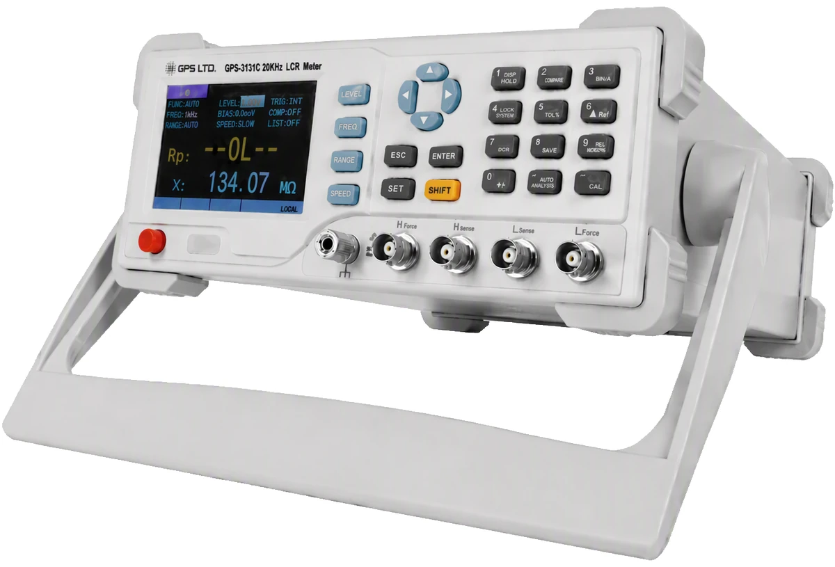
GPS-3131C Benchtop LCR Meter
10 Hz to 20 kHz, continuous · ±0.2% basic · five digits on both readings
Twelve frequencies sit on a shortcut key. They are the common ones, not the range. Underneath, the source steps by 1 Hz all the way from 10 Hz to 20 kHz, and the drive does the same from 100 mV to 2 V, so the conditions are yours to set rather than yours to pick from.
What you actually get to set
A component has no single value. It depends on the frequency, on the drive, and on what the source behind that drive looks like. All three are yours here, and all three are shown on screen with the reading.
Twelve on a key, twenty thousand on the dial
The twelve frequencies printed on the shortcut key are the common ones, not the range. The source runs from 10 Hz to 20 kHz and steps by 1 Hz, so a part is measured at the frequency it will work at rather than the nearest one somebody chose in advance.
- 10 Hz to 20 kHz
- Continuous, 1 Hz steps, accuracy ±0.02%
A drive you set, and a source you choose
Level is the same: six preset points on a key, but anywhere from 100 mV to 2 V in 1 mV steps underneath. Source impedance is selectable at 30 Ω or 100 Ω, which is what makes an inductor reading comparable with a figure taken on another instrument.
- 100 mV to 2 V
- Source impedance 30 Ω or 100 Ω
Three ways to look at the same part
AC measurement for L, C, R and Z. A DC resistance mode for the winding resistance of a coil or transformer. An electrolytic mode that respects polarity, red clip to the positive lead. Bias of up to 1500 mV puts a working voltage across the part while it is measured.
- AC · DCR · electrolytic
- Internal bias 0 to 1500 mV in 1 mV steps
Ranging can be left automatic or locked. Locking it after the first part of a batch saves the settling time on every one after that.
Measurement range
Two parameters are read in the same cycle, and either can be left on automatic, in which case the instrument works out whether it is holding an inductor, a capacitor or a resistor and picks the companion reading itself.
| Parameter | Range | Measured as |
|---|---|---|
| Inductance | 0.01 µH to 9999 H | Ls or Lp, with Q, D, X or phase |
| Capacitance | 0.01 pF to 9999 µF | Cs or Cp, with D, Q or ESR |
| Resistance, reactance and impedance | 0.0001 Ω to 99.99 MΩ | Rs or Rp, X and |Z| |
| DC resistance | 0.000 Ω to 99.99 MΩ | Eleven ranges, separate mode |
| Dissipation and quality | 0.0001 to 99999 | D and Q |
| Phase angle | ±180.000° | θ |
±0.2% is the basic figure and is stated at 23 °C ±5 °C, with open and short circuit calibration run and more than half an hour of warming. It degrades through three factors, one for measurement speed, one for drive level and one for frequency. The drive factor is at its best at 1 V and its worst at 100 mV, so the figure for a given case comes from the datasheet tables.
Deciding, not just measuring
Incoming inspection and production testing are the same measurement repeated with a verdict at the end of each. Both of these put the verdict on the screen and on the Handler, so nobody has to read a number.
Three bins, and somewhere for the rest
- Measure a part you are happy with and the nominal is taken from it, or type the value in.
- Set a high and low limit for each of three bins, from the preset 10, 25 and 50 percent points or entered anywhere from −99.99% to +99.99%.
- A part that passes on the main parameter but fails on the second goes to the auxiliary bin, and anything outside all three goes out. Pass and fail have separate tones.
The same part at seven frequencies
A scan takes up to seven frequencies in turn, each with its own upper and lower limit, and reports whether the reading fell inside, above or below at every one. In sequential mode a single trigger runs the lot; in stepping mode each trigger advances one point. Results go out through the Handler alongside an overall pass or fail for the whole sweep.
Triggering can be internal, from the front panel or from the Handler, so the instrument can be driven by whatever is feeding it parts.
Technical specifications
| Measures | Main parameter inductance, capacitance, resistance, impedance or automatic · second parameter reactance, dissipation factor, quality factor, phase angle or ESR · five digits on both |
|---|---|
| Basic accuracy | ±0.2% |
| Test frequency | 10 Hz to 20 kHz, continuously adjustable in 1 Hz steps · twelve preset points from 100 Hz to 20 kHz · accuracy ±0.02% |
| Test level | 100 mV to 2000 mV, continuously adjustable in 1 mV steps · six preset points · ±10% |
| Source impedance | 30 Ω or 100 Ω at ±1%, 100 Ω unless changed |
| DC bias | Internal 0 to 1500 mV in 1 mV steps at ±(5% + 20 mV) |
| Modes | AC measurement, DC resistance and electrolytic capacitor · series or parallel equivalent, switched for you when the main parameter is left on automatic |
| Measurement speed | Slow 2, medium 4 and fast 8 readings per second |
| Calibration | Open and short circuit calibration from the front panel |
| Recording | Maximum, minimum and average held while measuring · data hold · deviation against a reference reading |
| Sorting | Three pass bins with an auxiliary bin and an out-of-bin · preset limits at 10, 25 and 50% or entered from −99.99% to +99.99% in 0.01% steps · separate tones for pass and fail |
| List scan and trigger | Seven frequencies, each with its own upper and lower limit · sequential or stepping · trigger internal, manual or external |
| Interfaces | USB device, RS232 and Handler · SCPI command set · Handler is a nine-pin socket with five sorting outputs, an end of measurement output and a trigger input, 3 V to 25 V |
| Display | 3.5 in colour LCD · English interface · backlight 30, 50, 70 or 100% · settings restored at power on or returned to default |
| Power | 220 V AC ±10% or 110 V AC ±10%, chosen on a rear selector · 45 to 65 Hz · under 20 W |
| Environment and size | Operating 0 to 40 °C · humidity 15% to 85% · storage 5 to 40 °C · 265 × 105 × 305 mm, width by height by depth · 2.3 kg |
What’s in the box
- GPS-3131C meter
- Four-terminal Kelvin test clamp
- AC power cord
- Instruction manual and warranty certificate
Interfaces fitted, cables not
USB, RS232 and the Handler socket are all fitted as standard, but the leads for them are ordered separately. Worth adding to the order if the instrument is going onto a line or under software control, because there is no substitute in the box.