
GPS-135A
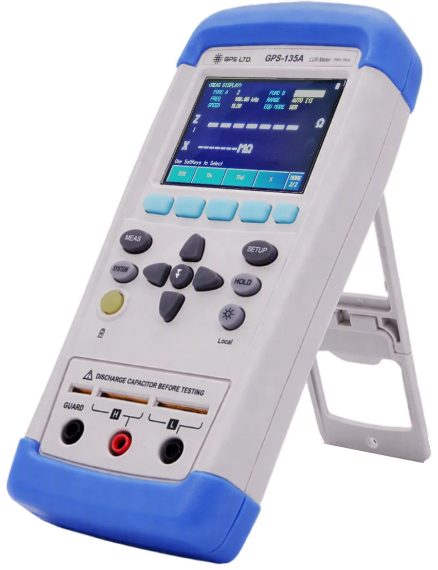
GPS-135A Handheld LCR Meter
L, C, R and Z · five frequencies to 100 kHz · ±0.2% basic
A measurement is only worth writing down if someone else can repeat it. This one states the conditions it was taken under and holds them: five fixed frequencies, 0.6 Vrms into a 100 Ω source, and the equivalent circuit named on screen beside the reading.
Three things decide the number
A component has no single value. What you read depends on how you asked, and an instrument earns its keep by letting you set that and then telling you what you set.
The frequency you test at
Five fixed points from 100 Hz to 100 kHz. A part is characterised where it will work: a smoothing capacitor near mains frequency, a decoupling capacitor or an RF choke at the top of the range. The 120 Hz point is actually 120.048 Hz, which matters when you are comparing against a published figure.
- 100 Hz to 100 kHz
- Five points, frequency accurate to 0.02%
The source behind the signal
The drive is 0.6 Vrms and the source impedance is held at 100 Ω. Stating both is what lets a number be compared: a reading taken here matches one taken on the same setting next month, and matches the one the next instrument gives.
- 0.6 Vrms into 100 Ω
- Level ±10%, source impedance ±5%
The circuit you assume
A real part is modelled as an ideal one with something in series or in parallel, and the choice changes the answer. Low impedance parts read best in series, high impedance parts in parallel. Left on automatic, the instrument picks.
- Series, parallel or auto
- Chosen on the instrument or left to it
All three sit on screen above the reading, so a figure copied into a report carries the conditions it was taken under.
Two readings, one cycle
The value on its own rarely settles anything. What tells you whether a part is any good is the loss beside it, and both are taken in the same measurement rather than one after the other.
| Measuring | Read alongside | What it tells you |
|---|---|---|
| Inductance | Q or D | How lossy the winding is at the frequency you chose |
| Capacitance | D or ESR | Dielectric loss, and the series resistance that heats an electrolytic and eventually kills it |
| Resistance | Q or θ | How far from purely resistive the part actually is |
| Impedance | θ or X | Magnitude with the phase angle, so reactance is separated from resistance |
Either can be left on automatic. The instrument works out whether what you have connected is an inductor, a capacitor or a resistor and picks the sensible companion reading, which is quicker when the part is unmarked.
Measurement ranges
Fine enough at the bottom for a few thousandths of a picofarad of stray, and wide enough at the top for a mains transformer winding or a supply reservoir.
| Parameter | Range | Finest resolution | Equivalent circuit |
|---|---|---|---|
| Inductance L | 0.001 µH to 999.9 H | 0.001 µH | Series or parallel |
| Capacitance C | 0.001 pF to 999.9 mF | 0.001 pF | Series or parallel |
| Resistance R | 0.0001 Ω to 99.99 MΩ | 0.1 mΩ | Series or parallel |
| Impedance Z and reactance X | 0.0001 Ω to 99.99 MΩ | 0.1 mΩ | With phase angle in degrees or radians |
Basic accuracy is ±0.2% and applies with correction run, at 23 °C ±5 °C, on the slower measurement rate and after half an hour warming. It holds across the middle of the ranges and falls away towards the extremes of frequency and impedance, so the figure for a particular range and frequency is the one in the datasheet tables rather than the basic figure.
Checking a batch, not a part
Goods-in work is the same measurement a hundred times with a decision at the end of each. The instrument makes the decision and leaves you holding the parts.
Type the nominal, then sort the tray
- Type the value straight onto the touch screen, or measure a part you are happy with and take that as the nominal.
- Pick a tolerance. One, five, ten or twenty percent on a key, or any figure entered directly.
- Every part after that reads pass or fail with its deviation as a percentage, and the beeper can sound on either result.
Correct, or the leads are in the reading
Open circuit correction removes the stray admittance between the leads, which otherwise sits on top of every small capacitor. Short circuit correction removes the residual impedance of the leads and contacts, which otherwise sits on top of every low value part. Both run from the setup page and are applied across the frequency points, and both need running again whenever the fixture or the leads change.
Holding the range rather than leaving it automatic speeds the cycle up, which is worth doing on a long batch of one value, and worth more at 100 Hz and 120 Hz than higher up.
Technical specifications
| Measures | Inductance, capacitance, resistance and impedance · second reading from dissipation factor, quality factor, ESR, phase angle or reactance · either can be left on automatic |
|---|---|
| Ranges | 0.001 µH to 999.9 H · 0.001 pF to 999.9 mF · 0.0001 Ω to 99.99 MΩ |
| Basic accuracy | ±0.2% |
| Test frequency | 100 Hz, 120.048 Hz, 1 kHz, 10 kHz and 100 kHz · frequency accuracy ±0.02% |
| Test level | 0.6 Vrms ±10% ±2 mV · source impedance 100 Ω ±5% |
| Equivalent circuit | Series, parallel or automatic |
| Secondary ranges | Dissipation 0.0001 to 9.999 · quality 0.0001 to 999.9 · phase angle ±179.99° or ±3.1416 rad |
| Ranging and speed | Automatic or held, five impedance ranges · slow 1.5 or fast 4 readings per second |
| Correction | Open circuit and short circuit correction, applied across the frequency points |
| Sorting | One comparator set on the main parameter · nominal typed in or taken from a reference part · tolerance 1, 5, 10 or 20%, or entered directly · beep on pass or on fail |
| Display | 2.8 in true-colour TFT with touch screen · English interface · 50,000 counts on the main and the second reading · brightness 30, 50, 70 or 100% · reading hold and keypad lock |
| Terminals | Five-terminal slot and three-terminal slot, with a guard terminal |
| Interface | Mini USB to a computer, no driver required · acquisition software supplied · documented command set for writing your own |
| Power | Rechargeable lithium battery · 9 V DC adapter, 90 to 250 V input · about 2 hours to charge · 14 hours at 30% brightness, 8 hours at full · dims and powers down after 5 to 30 minutes |
| Environment | Operating 0 to 40 °C · relative humidity 90% or less · altitude to 2000 m · storage −10 to 70 °C |
| Dimensions · weight | 195 × 90 × 41 mm, 35.5 mm across the case · 350 g |
| Compliance | IEC 61010-1 · IEC 61326-2-1 |
What’s in the kit
- GPS-135A meter, lithium battery fitted
- Four-terminal Kelvin test clip
- Mini USB communication lead
- 9 V DC power adapter
- Data acquisition software
- Instruction manual and warranty certificate
Kelvin clip in the box, not on the invoice
Four-terminal measurement is what keeps the lead resistance out of a low value reading, and the Kelvin clip that does it is supplied rather than sold separately. It plugs into the five-terminal slot; the three-terminal slot alongside takes a through-hole component pushed straight in, and a guard terminal is fitted for work where a third path would otherwise shunt the measurement.