
GPS-132C
GPS-132C Handheld LCR Meter
L, C, R and Z · six frequencies to 100 kHz · ±0.30% basic
A component does not have one value. Measure the same capacitor at 100 Hz and at 100 kHz and you get two different numbers, both of them correct. What this instrument gives you is control of the conditions, so the reading describes the part where it is actually going to work.
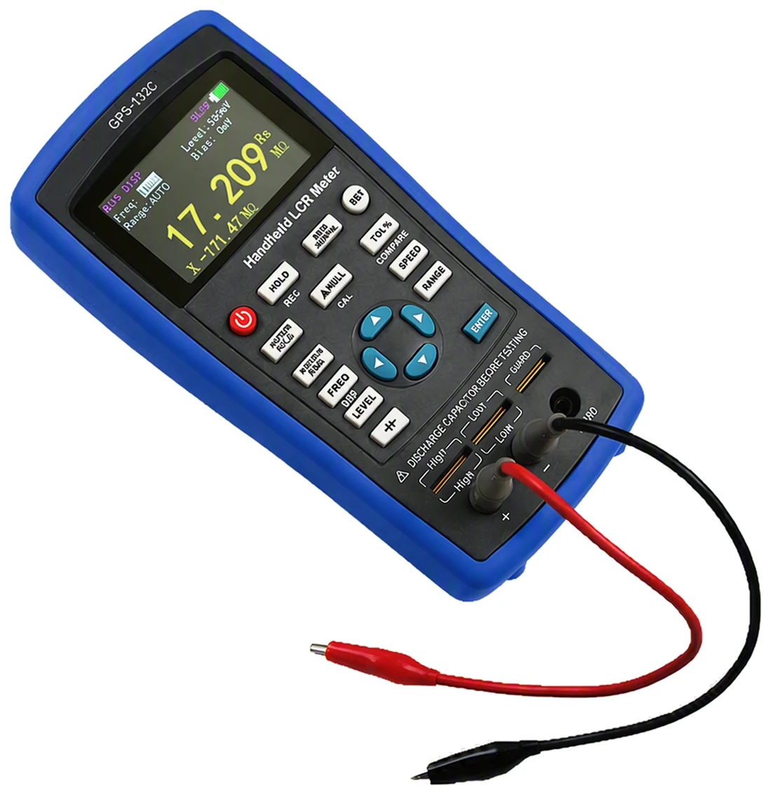
Three settings decide the number
This is the difference between a bridge and a component tester. A tester gives you a value. A bridge lets you say under what conditions, and then tells you what the part does under those.
The frequency you test at
Six fixed frequencies from 100 Hz to 100 kHz. A smoothing capacitor is characterised near mains frequency, a decoupling capacitor or an RF choke nearer the top of the range. Read a part at the wrong end and the number is real but not the one that matters.
- 100 Hz to 100 kHz
- Six settings: 100, 120, 1k, 10k, 40k and 100 kHz
The level you drive it with
Two test levels. Ferrites and electrolytics are not linear, and their value moves with how hard they are driven, so the level is stated with the reading rather than left to chance.
- 0.3 and 0.6 Vrms
- Selected on the instrument
The circuit you assume
Every real part is modelled as an ideal one with something in series or in parallel, and which you pick changes the answer. Low impedance parts read best in series, high impedance parts in parallel.
- Series or parallel
- Below about 100 Ω series, above 10 kΩ parallel
All three are shown on screen with the reading, so a result written down carries the conditions it was taken under.
Two readings, not one
The value on its own rarely settles anything. What tells you whether a part is any good is the loss that sits beside it, and both are on the screen together.
| Measuring | Read alongside | What it tells you |
|---|---|---|
| Inductance | Q or D | How lossy the winding is at the frequency you chose |
| Capacitance | D or ESR | Dielectric loss, and the series resistance that heats an electrolytic and eventually kills it |
| Resistance | Q or θ | How far from purely resistive the part actually is |
| Impedance | θ or X | Magnitude with the phase angle, so reactance is separated from resistance |
Left on automatic, the instrument works out for itself whether what you have connected is an inductor, a capacitor or a resistor, which is quicker when the part is unmarked.
Measurement ranges
Wide enough at the bottom for a few picofarads of stray, and at the top for a mains transformer winding or a supply reservoir.
| Parameter | Range | Finest resolution | Equivalent circuit |
|---|---|---|---|
| Inductance L | 0.000 µH to 2000 H | 0.001 µH | Series or parallel |
| Capacitance C | 0.000 pF to 20.000 mF | 0.001 pF | Series or parallel · electrolytic mode |
| Resistance R | 0.0001 Ω to 20.000 MΩ | 0.1 mΩ | Series or parallel |
| Impedance Z | 0.0001 Ω to 20.000 MΩ | 0.1 mΩ | With phase angle |
Basic accuracy is ±0.30% and holds over the middle of the range. It falls away towards the extremes of frequency and impedance, so the figure that applies to a particular range is the one in the datasheet tables rather than the basic figure.
Checking a batch, not a part
Goods-in work is not one measurement, it is the same measurement a hundred times with a decision at the end of each. The instrument makes the decision and leaves you holding the parts.
Set the nominal, then sort the tray
- Measure a part you are happy with, or type the nominal in directly.
- Choose a tolerance band. Fixed points at 1, 5, 10 and 20%, or anything from 1% to 50%.
- Every part after that reads pass or fail, with how far out it is as a percentage.
Correct, or the leads are in the reading
Open circuit correction removes the capacitance between the leads, which otherwise sits on top of every small capacitor you measure. Short circuit correction removes the lead and contact resistance, which otherwise sits on top of every low value part. Both run from the front panel, and the relative mode will null against a reference component as well.
Maximum, minimum and average are held while measuring, so a part that drifts under the probe is caught rather than averaged away by eye.
Technical specifications
| Measures | Inductance, capacitance, resistance and impedance · second reading from reactance, dissipation, quality factor, phase angle or ESR · automatic selection of the main parameter |
|---|---|
| Ranges | 0.000 µH to 2000 H · 0.000 pF to 20.000 mF · 0.0001 Ω to 20.000 MΩ |
| Basic accuracy | ±0.30% |
| Test frequency | 100 Hz, 120 Hz, 1 kHz, 10 kHz, 40 kHz and 100 kHz |
| Test level | 0.3 Vrms and 0.6 Vrms |
| Equivalent circuit | Series or parallel, selected on the instrument |
| Electrolytic mode | Fitted, for polarised capacitors |
| Ranging | Automatic, or held at 100 Ω, 1 kΩ, 10 kΩ or 100 kΩ |
| Measurement speed | 1, 2 or 4 readings per second |
| Correction | Open circuit and short circuit correction from the front panel · relative mode against a reference part |
| Sorting | Nominal and tolerance from 1% to 50%, fixed points at 1, 5, 10 and 20% · pass or fail shown with the deviation as a percentage |
| Recording | Maximum, minimum and average held while measuring · reading hold |
| Display | 2.8 in colour TFT · English interface · five digits on the main and the second reading · adjustable brightness |
| Interface | Mini USB to a computer · SCPI command set |
| Power | Rechargeable 5 V 2600 mAh lithium battery, charged over USB · automatic power off, time adjustable |
| Environment | Operating 0 to 40 °C · relative humidity 15% to 85% · pollution degree 2 · indoor use below 2000 m |
| Dimensions · weight | 192 × 91 × 52.5 mm · 365 g |
What’s in the kit
- GPS-132C meter, lithium battery fitted
- Alligator clip test leads with rubber plugs
- Short circuit bar
- Mini USB communication lead
- Power adapter
- Instruction manual and warranty certificate
Kelvin clips and SMD tweezers
The supplied leads are right for through-hole parts and general work. For low value parts, where the lead resistance would otherwise be a large share of the reading, a four-terminal Kelvin fixture is available separately, along with tweezers for surface mount components. Both are worth having if you measure below an ohm or work with anything smaller than 0805.