Winding Resistance Tester · Test & Measurement
WRT‑5660
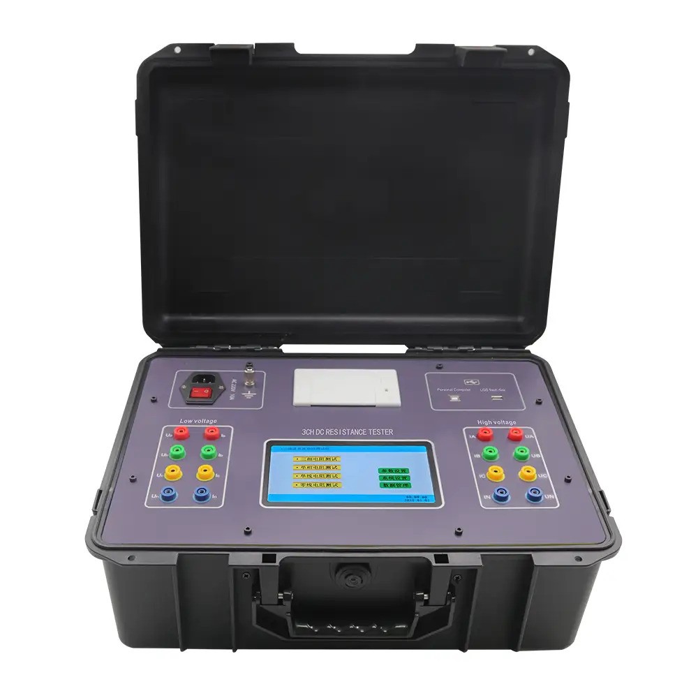
Three‑phase DC winding resistance tester for power transformers and other low‑ohmic applications — 4‑wire Kelvin measurement, selectable test currents 0.2/0.5/2/5/10/20 A, assisted de‑magnetisation, temperature conversion, automatic 3‑phase unbalance display, 7″ touchscreen, built‑in printer and 500‑set memory.
0.1 µΩ–5000 Ω range±0.2%FS ±5 dgtResolution 0.001 mΩ
0.2–20 A (6 steps)Max 20 A / 27 V1200 W rating
4‑wire Kelvin7″ touchscreenPrinter & 500 sets
Test hookup diagrams — WRT-5660
Single winding — 4-wire Kelvin
 -->
<path d='M 350 90 C 300 90 260 120 220 120' fill='none' stroke='%23ff4d4d' stroke-width='3'/>
<circle cx='220' cy='120' r='3' fill='%23ff4d4d'/>
<path d='M 350 120 C 300 120 120 120 58 120' fill='none' stroke='%23222' stroke-width='3'/>
<circle cx='58' cy='120' r='3' fill='%23222'/>
<!-- Sense leads (thin) - connect inside the current contacts to avoid lead drop -->
<path d='M 430 90 C 380 70 300 80 230 112' fill='none' stroke='%23ffa64d' stroke-width='2' stroke-dasharray='5,4'/>
<circle cx='230' cy='112' r='3' fill='%23ffa64d'/>
<path d='M 430 120 C 380 140 130 140 48 112' fill='none' stroke='%23666' stroke-width='2' stroke-dasharray='5,4'/>
<circle cx='48' cy='112' r='3' fill='%23666'/>
<!-- Notes -->
<text x='40' y='170' font-size='12' fill='%23456'>Place V-sense clips</text>
<text x='150' y='170' font-size='12' fill='%23456'>inside</text>
<text x='190' y='170' font-size='12' fill='%23456'>the current clips</text>
<text x='40' y='186' font-size='12' fill='%23456'>to eliminate lead drop (Kelvin).</text>
</svg>)
- Connect I+ / I- to the winding ends (H, X).
- Clip V+ / V- inside the current clips (Kelvin) to remove lead resistance.
- Select suitable test current (e.g., 2–20 A for power transformers), start test, wait for stabilisation.
Tip: For large windings, start with a lower current to check heating, then increase.
Three-phase overview

- Measure phases A, B, C in sequence with the same current.
- Use the instrument’s unbalance display to compare results directly.
- If needed, run de-magnetisation between tests on large cores.
Tip: Apply temperature conversion for like-for-like comparisons against nameplate.