
HVT-2800
HVT-2800 Wireless High Voltage Phase Detector
30 V to 550 kV · 0.1° resolution · about 200 m wireless
Before two circuits are paralleled somebody has to prove they are in phase, and the two conductors are rarely side by side. A detector hooks over each, both report back to one receiver over a 2.4 GHz link, and the receiver states the answer aloud as well as showing it.
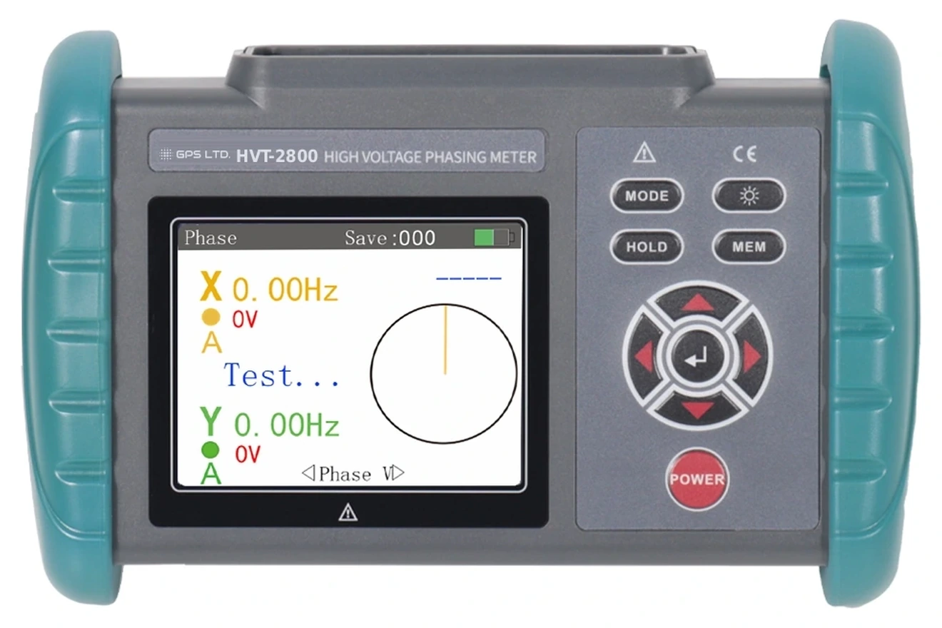
Receiver · 187 × 119 × 48 mm, 350 g
Two conductors, one reading
Phasing needs two measurements taken at the same instant on conductors that may be a bay apart. A detector goes on each, and the receiver does the comparing.
- The detectors
- X and Y hook over the conductors. The electric field around a live line induces the signal, so nothing has to be clamped or cut into.
- The link
- 2.4 GHz back to the receiver, reaching about 200 m, so the two conductors need not be near one another and one operator reads both.
- The verdict
- Phase angle, phase sequence and frequency on one screen, as a phasor diagram and as figures, and spoken aloud.
Contact or non-contact
Which method you may use is set by the conductor, not by preference. Two things decide it: whether the conductor is bare, and whether it is above 35 kV.
Bare below 35 kV, or insulated below 550 kV
The hook may touch the conductor. Contact gives the strongest signal and the quickest acquisition.
- Bare conductor below 35 kV
- Insulated conductor below 550 kV
- Detector hooked directly over the line
Bare conductor above 35 kV
The probe is brought gradually towards the line until the field is sensed, and never makes contact. This is a requirement, not a recommendation.
- Bare conductor above 35 kV
- Probe approaches, does not touch
- Insulating rod sets the working clearance
Two telescopic rods are supplied at 3 m extended, tested at AC 220 kV rms end to end after stretching. The rods are what establish the clearance, so they are checked before every use.
Reading the result
The phase angle is measured across the full 0 to 360° to 0.1°, and the instrument states which side of the line it falls.
The spoken output confirms each detector before it gives a verdict, so a result can be told apart from a detector that never acquired a signal. That matters when the rod is at height and you are watching the conductor rather than the screen. 500 readings are stored for the record.
Technical specifications
| Line voltage | 30 V to 550 kV |
|---|---|
| Phase | 0.0 to 360.0° · precision ≤ ±10° · resolution 0.1° |
| Frequency | 30.00 to 100.0 Hz · precision ≤ ±1 Hz · resolution 0.01 Hz |
| Verdict | In phase 330 to 360° and 0 to 30° · out of phase 90 to 150° and 210 to 270° |
| Wireless link | 2.4 GHz between each detector and the receiver · about 200 m integrated transmission distance |
| Display | 3.5 inch colour screen, 72 × 55 mm · phasor diagram and figures shown together · English interface |
| Indication | Spoken prompts confirming each detector signal and the verdict · red and green indicators · audible tone |
| Memory | 500 groups, with recall of the stored history · FULL flashes when the memory is full |
| Power | Receiver and each detector carry a built-in 3.7 V rechargeable lithium battery · shuts down after about 15 minutes idle |
| Consumption | Receiver 300 mA maximum · each detector 80 mA maximum |
| Insulating rods | Two, 3 m extended, Φ38 mm maximum diameter · both ends tested at AC 220 kV rms after stretching |
| Insulation | Receiver and detectors withstand AC 3700 V rms between exposed metal and the plastic casing |
| Compliance | IEC 61481:1999/AMD2:2004 · IEC 61243-1 ed. 2:2003 |
| Environment | Operating −10 to 40 °C below 70% RH · storage −10 to 60 °C below 80% RH |
| Dimensions | Receiver 187 × 119 × 48 mm · detector 52 × 31 × 114 mm |
| Weight | Receiver about 350 g with battery · each detector about 150 g with hook and battery |
What’s in the case
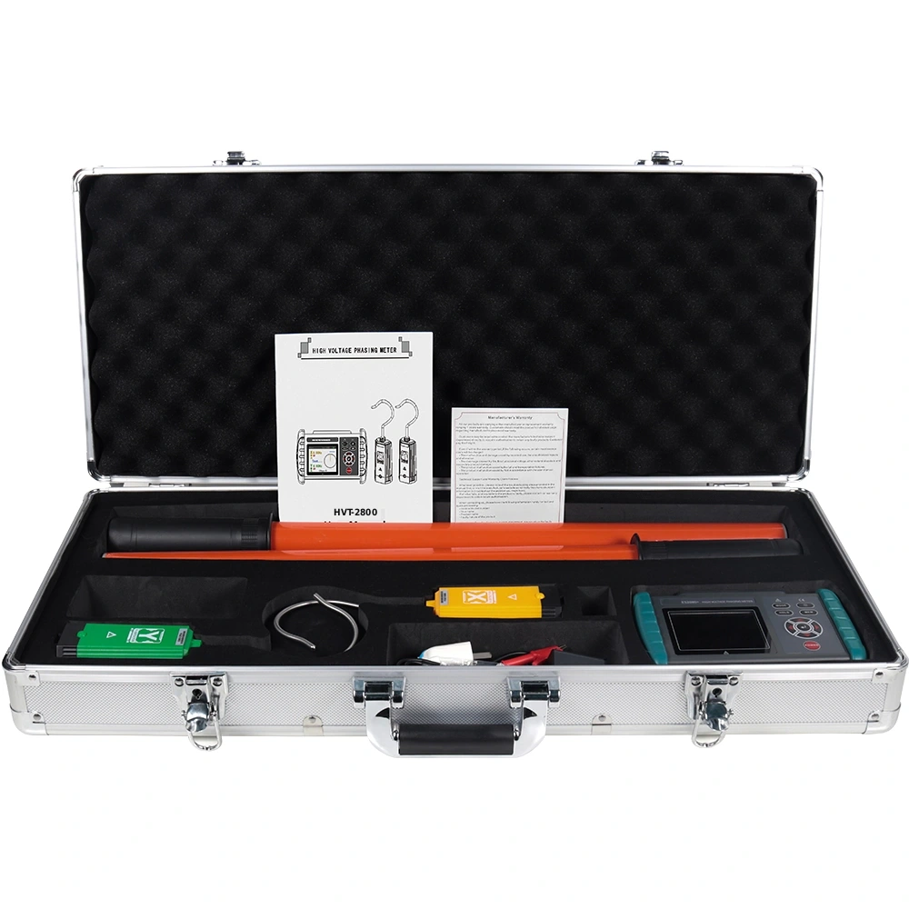
- HVT-2800 receiver, one
- Detectors, two, each with hook and probe
- Telescopic insulating rods, two, 3 m
- Three-way charger and inspection lead
- Manual, warranty card and certificate
- Aluminium instrument case
Both detectors are supplied, so the set is complete as delivered. The rods extend to 3 m and are tested at AC 220 kV rms end to end.