
CBA-III
CBA-III Circuit Breaker Analyser
12 contacts · travel and speed · coil current · action voltage
A mechanical characteristics tester for vacuum, SF6, minimum-oil and bulk-oil switchgear. One operation of the breaker captures the whole picture: timing on twelve contacts, travel and speed, coil current and the resulting waveforms, rather than a separate test for each.
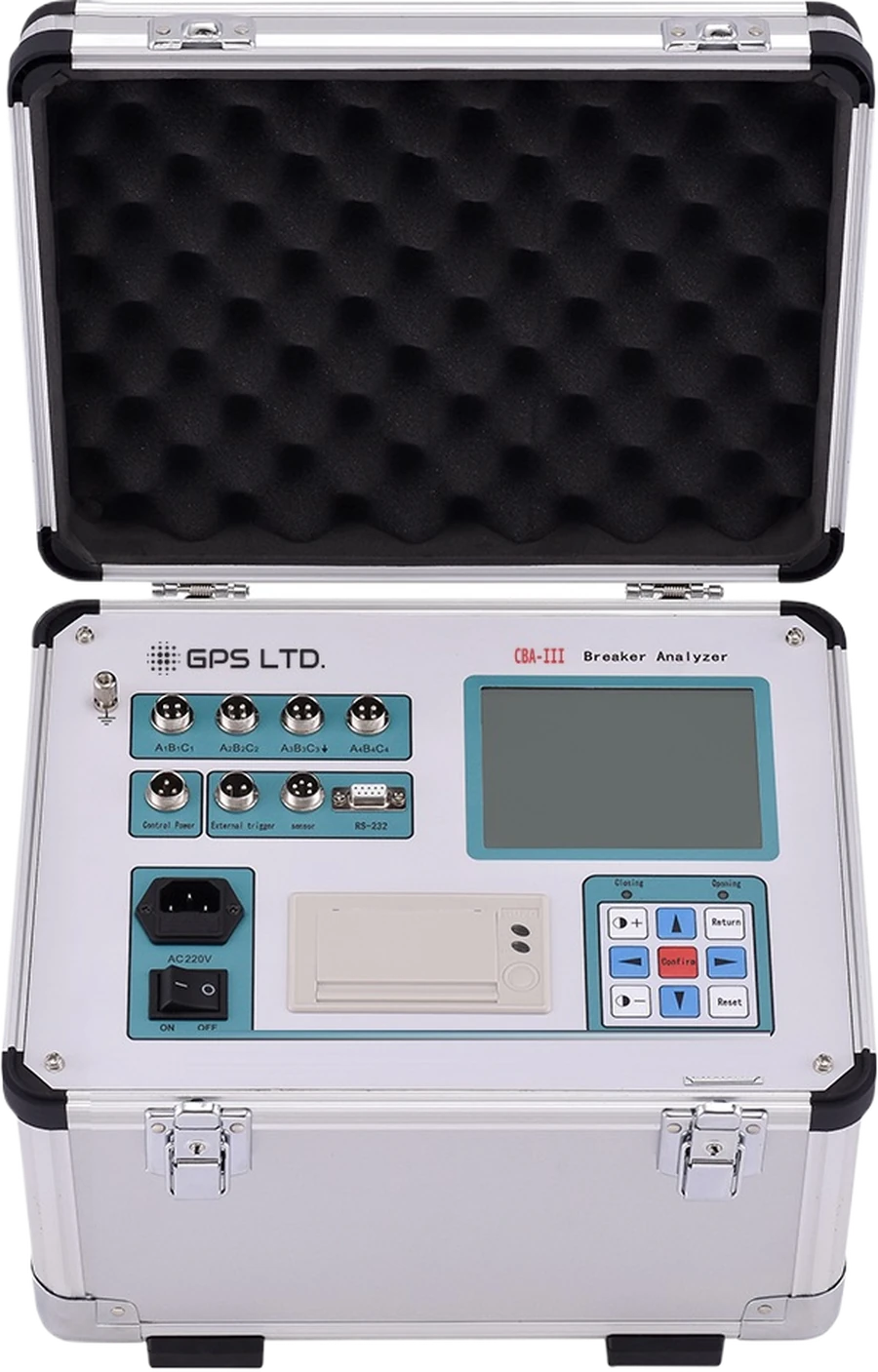
One operation, the whole picture
Trip the breaker once and the analyser records timing, travel, speed, bounce and coil current together, so every number comes from the same operation rather than from a separate test each time.
Twelve contacts at once
Four three-phase sockets, A₁B₁C₁ to A₄B₄C₄, so multi-break interrupters are timed in a single operation with phase discrepancy to ±0.1 ms.
Reclosing sequences
C-O, O-C and O-C-O with their process times: first opening, first closing, second closing, metallic short-circuit time and no-current time.
Travel, speed and bounce
Total travel, opening travel, over-travel, overrun and rebound, with instantaneous and maximum speed and the time against travel curve.
Built-in action voltage supply
DC 30 to 250 V digitally adjustable at 20 A drives the mechanism and runs the low-voltage action test automatically.
Coil current waveforms
Opening and closing coil current to 20.00 A with the waveform, which is what separates a sticking mechanism from a failing coil.
Prints at the switchgear
A thermal printer in the lid gives a record on paper without a laptop, and results also transfer over RS-232 for the report.
For vacuum, SF6, minimum-oil and bulk-oil switchgear. The travel sensor is matched to the mechanism, so tell us the breaker type and we will confirm which one you need.
Three traces that tell you what is wrong
The numbers say whether the breaker passed. The traces say why it did not, and which part of the mechanism to look at.
Timing
Contact trace · discrepancy
Open and close instants on every contact, with in-phase and out-of-phase discrepancy and the bounce that follows.
Motion
Travel curve · over-travel
Displacement against time, giving speed at any point, over-travel past the contact position and the rebound that follows.
Drive
Coil current · armature release
The armature notch, the current peak and the release point. A coil that draws correctly but never releases shows up here first.
All three are captured from the single operation and shown on the backlit display, printed at the switchgear, or transferred over RS-232 for the report.
Measurement ranges and accuracy
Timing and coil current are fixed. Travel is not: the range and resolution follow the sensor matched to the mechanism, so the figures below are by breaker type rather than by switch setting.
| Parameter | Range | Resolution | Accuracy |
|---|---|---|---|
| Timing | |||
| Contact timing, below 100 ms | 0 to 4000.0 ms | 0.1 ms | ±(0.1 ms + 1 digit) |
| Contact timing, 100 ms and above | 0 to 4000.0 ms | 0.1 ms | ±(0.1% rdg + 1 digit) |
| Phase discrepancy | Within the timing range | 0.1 ms | ±0.1 ms |
| Travel and speed · the travel range follows the sensor matched to the mechanism | |||
| Speed, 0 to 2 m/s | 0 to 20.00 m/s | 0.01 m/s | ±(0.1 m/s + 1 digit) |
| Speed, above 2 m/s | 0 to 20.00 m/s | 0.01 m/s | ±(0.2 m/s + 1 digit) |
| Travel, vacuum breaker | 0 to 50.0 mm | 0.1 mm | ±(1% rdg + 1 digit) |
| Travel, SF6 breaker | 0 to 300.0 mm | 1 mm | ±(1% rdg + 1 digit) |
| Travel, minimum-oil breaker | 0 to 600.0 mm | 1 mm | ±(1% rdg + 1 digit) |
| Coil current and action voltage | |||
| Coil current, opening and closing | 0 to 20.00 A | 0.01 A | Waveform captured |
| Action voltage supply | DC 30 to 250 V | Digitally adjustable | 20 A, instantaneous duty |
Travel range and resolution follow the breaker type, because they depend on the sensor matched to the mechanism rather than a switch setting. The low-voltage action test runs from the instrument’s own adjustable DC supply and reports the voltage at which the mechanism actually operates, rather than confirming that it operates at nominal.
Technical specifications
| Timing | Opening and closing time on 12 contacts · in-phase and out-of-phase discrepancy · fixed times per contact |
|---|---|
| Reclosing | C-O, O-C and O-C-O per breaker, with first opening, first closing, second closing, metallic short-circuit and no-current times |
| Bounce | Closing bounce time and count per pole, with the bounce waveform · rebound magnitude per pole |
| Speed | Instantaneous opening and closing speed · maximum speed · time against travel characteristic curve |
| Travel | Total travel, opening travel, over-travel, overrun and rebound magnitude |
| Coil current | Opening and closing coil current with the current waveform |
| Action voltage | Automatic low-voltage action test, reporting the voltage at which the mechanism operates |
| Contact inputs | 12 contacts on four three-phase sockets, A₁B₁C₁ to A₄B₄C₄ |
| Other connections | Control power output · external trigger input · travel and speed sensor input · RS-232 |
| Output supply | DC 30 to 250 V digitally adjustable, 20 A instantaneous duty |
| Results | Built-in thermal printer · internal storage with real-time clock · backlit LCD with waveform display |
| Interference | Holds accuracy alongside 500 kV substations and live busbars |
| Insulation | Supply to chassis withstands 1.5 kV at power frequency for one minute with no flashover or arcing · insulation resistance above 2 MΩ |
| Power | AC 220 V ±10%, 50 Hz ±10% |
| Environment | Operating −10 to 40 °C · humidity 80% RH or below · 86 to 106 kPa |
| Dimensions · weight | 360 × 280 × 300 mm · 9 kg · aluminium flight case with a foam-lined lid |
What’s in the kit
- CBA-III analyser in its aluminium flight case
- Contact test leads for four three-phase groups
- Travel and speed sensor for the mechanism type
- Control power and external trigger leads
- RS-232 lead and PC software
- Mains lead, manual and warranty certificate
Two lead sets, 10 m each
One set for the high voltage side and one for the low, colour coded to the A, B and C terminals. Ten metres per set is what lets the instrument sit clear of a tank while both windings stay connected, and it is why the leads weigh more than the instrument does.