
GPS-9020 series
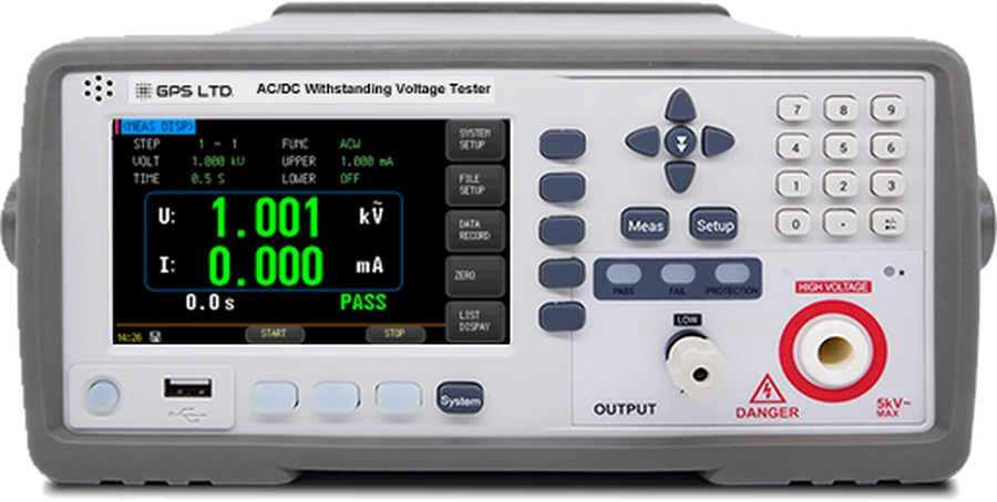
GPS-9020 Series AC/DC Withstand & Insulation Tester
ACW 5 kV · DCW 6 kV · IR 10 GΩ · 16-step sequences
A bench safety tester for production lines and compliance work. AC withstand, DC withstand and insulation resistance run individually or chained into a single automatic sequence, so a unit is proved in one pass rather than three separate set-ups.
One pass, not three set-ups
Proving a unit usually means a withstand test, then another, then an insulation check, each with its own connection. Chained into a plan they run as one sequence on one connection.
One test at a time
AC withstand, then re-cable and run DC withstand, then re-cable again for insulation resistance. Three connections, three chances to get one wrong, and three records to reconcile afterwards.
- Three passes
- Each with its own set-up and its own paperwork
Sixteen steps, one connection
Chain the tests into a plan and the instrument runs them in order on a single connection. Every step carries its own function, voltage, limits, ramp and dwell, and the results are listed step by step at the end.
- One pass
- Ten plans stored, up to sixteen steps each
Rise, test and fall are set separately from 0.1 to 999.9 s, so a capacitive load can be ramped gently and still dwell only as long as the standard requires. A 25-way Handler port and an RS-232C SCPI command set let the line act on the verdict without an operator reading a meter.
Three models, one platform
Same case, display, interfaces, timing and protection throughout. They differ only in which of the three tests is fitted.
GPS-9020A
AC withstand, 5 kV
AC withstand at 5 kV and 20 mA. The straightforward choice where the standard calls for a dielectric strength test and nothing more.
- Part number
- 869020
GPS-9020AD
AC and DC withstand
Adds DC withstand at 6 kV and 10 mA, for capacitive assemblies where a DC test avoids the charging current an AC test would draw.
- Part number
- 869068
GPS-9020ADI
AC, DC and insulation
Adds insulation resistance at 1 kV to 10 GΩ, so withstand and IR run in one sequence on the same connection.
- Part number
- 869164
The test functions are fitted at build and cannot be added later, so it is worth being sure before the order goes in. Insulation resistance is only available on the model that also has DC withstand, so choosing IR brings both. Tell us the standard you test to and we will confirm the model.
Protection that acts before you do
Five kilovolts on a production line is a hazard whoever is holding the part. These are the things that stop the output without waiting for a person.
Ground fault interrupter
More than 0.5 mA returning through the chassis and the output is killed within 0.3 s, with GFI on the display. It can be switched off; it is worth leaving on.
Arc detection
Nine levels on both AC and DC, at 20, 18, 16, 14, 12, 10, 7.7, 5.5 and 2.8 mA, so sensitivity is set to a real current rather than a vague scale.
Short-circuit trip
Trips at twice rated output current, or 1.5 times peak on AC.
Automatic discharge
After every test, 0.2 s, enough to bring 1 µF charged at 6 kV down to 30 V before anyone touches anything.
Judgement built in
Upper and lower current limits give HI FAIL and LOW FAIL, with PASS, FAIL and TEST lamps and a beeper. The instrument decides, not the operator.
Duty cycle
Above 6 mA AC or 3 mA DC, limit output to one minute and rest at least as long again.
The Handler port carries INTERLOCK, so a guard or a fixture lid can hold the output off as a condition of the test running at all.
Measurement ranges and accuracy
Voltage resolution is 1 V throughout. Which groups apply depends on the model fitted.
| Parameter | Range | Resolution | Accuracy |
|---|---|---|---|
| AC withstand voltage · all models | |||
| Output voltage | 0.050 to 5.000 kV | 1 V | ±(2% rdg + 5 digits) |
| Test current | 0.001 to 20.00 mA | 0.001 / 0.01 mA | ±(2% rdg + 5 digits) |
| Frequency | 50 or 60 Hz | — | ±0.1% |
| Output waveform | Sine | — | Distortion below 3%, resistive load |
| Load regulation | No load to full load | — | ±(2% rdg + 5 V) |
| DC withstand voltage · GPS-9020AD and 9020ADI | |||
| Output voltage | 0.050 to 6.000 kV | 1 V | ±(2% rdg + 5 digits) |
| Test current | 0.1 µA to 10.00 mA | 0.1 µA / 0.01 mA | ±(2% rdg + 5 digits) |
| Insulation resistance · GPS-9020ADI | |||
| Output voltage | 0.050 to 1.000 kV | 1 V | ±(1% rdg + 2 digits) |
| Measuring range | 0.02 MΩ to 10 GΩ | — | Depends on test voltage, see below |
| Current range | Auto, or 1 µA to 5 mA fixed | — | Fixed ranges speed the test up |
| Timing · all models | |||
| Rise and fall | 0.1 to 999.9 s each, or off | — | — |
| Test time | 0.2 to 999.9 s ACW · 0.1 to 999.9 s DCW and IR, or unlimited | — | — |
Insulation accuracy depends on the test voltage. At 500 V and above, 1 MΩ to 1 GΩ is ±(5% rdg + 5 digits) and 1 to 10 GΩ is ±(10% rdg + 5 digits). Below 500 V, 0.1 MΩ to 1 GΩ is ±(10% rdg + 5 digits), and the 1 to 10 GΩ band is indicative only with no accuracy specified. Auto ranging adds switching time, so a test takes at least one second.
Technical specifications
| Tests | AC withstand on all models · DC withstand on the AD and ADI · insulation resistance on the ADI · fitted at build and not addable later |
|---|---|
| Test plans | 10 stored internally, up to 16 steps each · every step has its own function, voltage, limits, timing and arc level |
| Display | 5 inch colour touch LCD with a 32-bit ARM processor · keypad and cursor keys · English interface |
| Accounts | Administrator and operator · operator changes are not saved |
| Judgement | Upper and lower current limits, HI FAIL and LOW FAIL · short-circuit trip · PASS, FAIL and TEST lamps with beeper |
| Results | Listed step by step at the end of a run, and recallable from the data record |
| Handler (PLC) | 25-way: START, STOP, TEST, PASS, FAIL, INTERLOCK · +24 V at up to 1 A for lamps and solenoids |
| RS-232C | 8 data bits, 1 stop bit, no parity · SCPI command set · DB-9 straight-through, 2 m maximum |
| File storage | 10 files internally, or to a USB stick on the front panel |
| Protection | Ground fault interrupter at 0.5 mA, output off within 0.3 s · arc detection, nine levels · short-circuit trip · automatic discharge, 0.2 s |
| Power | 110 V or 220 V AC ±10%, rear panel switch · 300 VA maximum · fuse 5 A at 110 V, 3 A at 220 V |
| Environment | Operating 10 to 40 °C at 10 to 80% RH · specified 18 to 28 °C · altitude to 2000 m |
| Duty cycle | Above 6 mA AC or 3 mA DC, limit to one minute on and rest as long again |
| Dimensions · weight | 293.8 × 130 × 447.9 mm with handle · 246 × 112 × 422.3 mm without · about 8 kg |
| Part numbers | GPS-9020A 869020 · GPS-9020AD 869068 · GPS-9020ADI 869164 |
What’s in the kit
- GPS-9020A, 9020AD or 9020ADI tester
- Withstand voltage test lead
- Withstand voltage earth lead
- RS-232 interface cable, DB-9, for the test PC
- Mains lead and two 3 A slow-blow fuses
- Printed user manual
Two lead sets, 10 m each
One set for the high voltage side and one for the low, colour coded to the A, B and C terminals. Ten metres per set is what lets the instrument sit clear of a tank while both windings stay connected, and it is why the leads weigh more than the instrument does.