
GPS-5030EC
GPS-5030EC Earth Continuity Tester
3 to 30 A · 0 to 600 mΩ · four-terminal Kelvin
A continuity check at a few milliamps will pass a joint that cannot carry fault current. This one forces up to 30 A through the protective earth path and reads the bond in milliohms, then judges it against a window and says so in about a second.
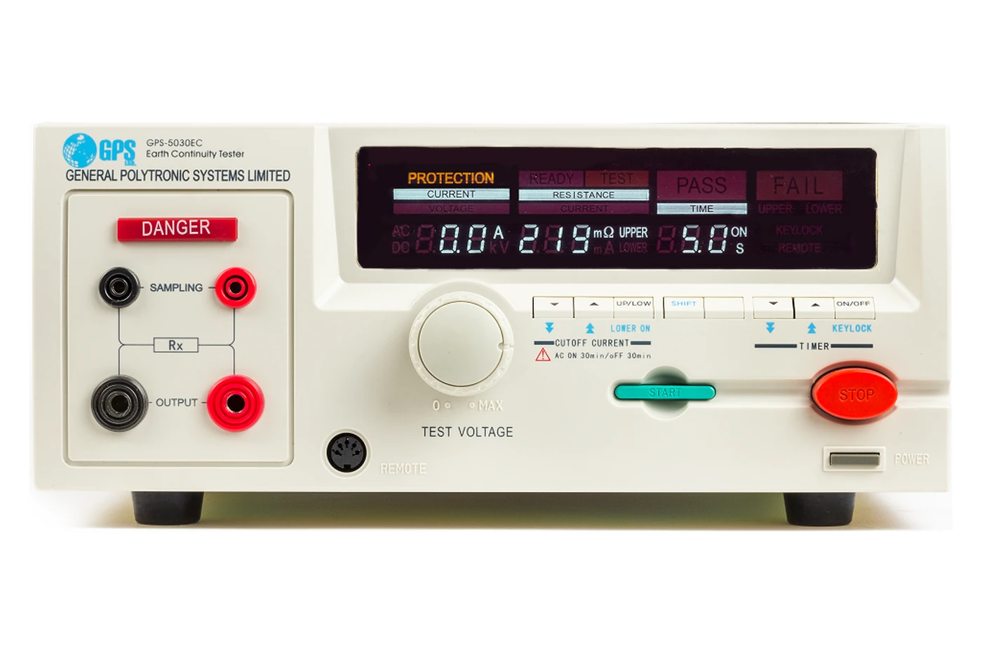
GPS-5030EC · 380 × 320 × 130 mm, 10 kg
Why four terminals
A good bond is a few tens of milliohms. So is a metre of test lead. Measure with two wires and you are largely measuring your own leads, which is why this instrument uses four and prints the diagram on its front panel.
- The current pair
- OUTPUT drives up to 30 A through the earth path. Whatever resistance the leads and clips add here does not matter, because the current is held constant regardless.
- The sense pair
- SAMPLING measures the volt drop across the bond alone. Almost no current flows in these leads, so they contribute almost no error.
- What is left over
- Whatever the fixture still adds is nulled with the resistance offset before testing starts, so the reading is the product and nothing else.
Choosing the current
Pick the current your standard calls for first, then check the resistance you expect falls under the ceiling for it. The output has to develop the volt drop across the bond, so the higher the current, the lower the resistance it can reach.
Anywhere from 3.0 to 30.0 A can be set in 0.1 A steps. The four figures above are the published points; between them the ceiling moves the same way. If a reading sits close to the limit for your chosen current, drop the current a step and the headroom returns.
Two limits, three verdicts
Both an upper and a lower limit are set, anywhere across the full 0 to 600 mΩ span. A single threshold would pass a shorted fixture; a window does not.
Inside the window
The reading sits between the lower and upper limits for the whole test time. The instrument holds the result, sounds the pass tone and lights PASS.
Resistance too high
A poor joint, a corroded contact, a screw that was never tightened, or a bond that simply is not there. The display distinguishes this from a low fail.
Resistance too low
Usually not the product. A shorted fixture, a probe clipped to the wrong point, or leads still shorted together from the offset null.
The display carries UPPER and LOWER as separate indications, so an operator can tell a bad product from a bad connection without reading the number. An open circuit raises its own alarm the instant it is detected.
On the line
Built to be started by something other than a person
This is a station rather than a handheld. The test runs to a set time, returns a verdict on its own, and can be driven from a controller so the operator only presents the product.
- Remote port
- A front-panel DIN connector takes start and stop from a PLC or a foot switch, so the cycle can be tied to a fixture closing.
- RS232
- Settings and results over a serial link to a PC or test controller.
- Timed cycle
- 0.5 to 999.9 s in 0.1 s steps, or continuous. The instrument ends the test and judges it without intervention.
- Keylock
- Locks the front panel so a set-up cannot be changed by accident once the line is running.
Technical specifications
| Ground resistance | 0.0 to 600 mΩ · ±(2% rdg + 0.3 mΩ) · 0.1 mΩ resolution · four-terminal Kelvin measurement |
|---|---|
| Limit settings | Upper and lower, each 0.0 to 600 mΩ · ±(2% set + 0.3 mΩ) · 0.1 mΩ resolution |
| Test current | 3.0 to 30.0 A · measured ±(2% rdg + 0.2 A), set ±(2% set + 0.2 A) · 0.1 A resolution · true RMS |
| Output | Sine wave, crest factor 1.3 to 1.5 · distortion below 2% on no load or a pure resistive load · 50 Hz or 60 Hz, selectable |
| Maximum resistance | 200 mΩ at 30.0 A · 270 mΩ at 25.0 A · 390 mΩ at 20.0 A · 600 mΩ at 10.0 A |
| Test time | Set 0.5 to 999.9 s, or 0 for continuous · ±(0.2% set + 0.05 s) · measured ±(0.1% set + 0.05 s) · 0.1 s resolution |
| Duty cycle | AC on 30 minutes, off 30 minutes, as marked on the front panel |
| Judgement | Window comparator against upper and lower limits · separate UPPER and LOWER fail indications · audible and visual alarm |
| Protection | Instant alarm if the earth path is open circuit · PROTECTION annunciator on the display |
| Offset | Adjustable resistance offset, to null the fixture and leads before testing |
| Display | Vacuum fluorescent, showing test current, resistance and elapsed time together, with READY, TEST, PASS, FAIL, KEYLOCK and REMOTE annunciators |
| Controls | Front-panel output control · UP / LOW and SHIFT keys · timer ON/OFF · keylock · START and STOP |
| Interfaces | RS232 · remote control port on a front-panel DIN connector for start and stop from a line controller |
| Power | 220 V AC ±10%, single phase, 47 to 63 Hz · fuse 5 A / 250 V AC |
| Environment | Operating 0 to 40 °C · relative humidity 75% or below |
| Dimensions · weight | 380 × 320 × 130 mm (l × w × h) · 10 kg |
| Part number | 861030 |