
ERT-10
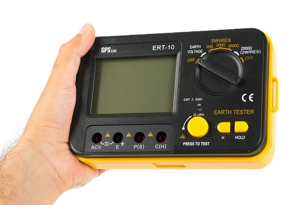
ERT-10 Earth Resistance Tester Kit
3-wire and 2-wire · 20 to 2000 Ω · 0.01 Ω resolution
Drive two spikes, connect the electrode and read its resistance. The fall-of-potential method is the reference way to measure a single earth electrode, which a clamp tester cannot do because a lone electrode forms no loop. Everything travels in one bag with the lead reels and spikes.
What it does
A clamp tester is quicker, but it needs a loop. For a single electrode, or a new installation before anything is bonded to it, spikes in the ground are the only way to get a real number.
Three-wire and two-wire
Precise three-wire fall-of-potential with two spikes, or a simplified two-wire test when only one can be placed.
3 mA test current
Low enough not to trip an RCD on the circuit under test, at about 820 Hz so mains hum does not corrupt the reading.
0.01 Ω resolution
Three ranges to 2000 Ω, reading to 0.01 Ω at the bottom where a good electrode should sit.
Earth voltage first
A separate dial position with its own ACV input. Stray ground potential corrupts a resistance reading, so check it before you measure.
Hands-free LOCK
PRESS TO TEST locks down for continuous measurement, so you can hold the leads instead of the button.
Backlit and holds
1999-count backlit LCD for pits and risers, data hold, HV indicator lamp, low battery warning and auto power off.
How the three-wire test works
1 · Place the spikes
Drive the two auxiliary spikes into the ground in a line with the electrode under test, five to ten metres apart. Damp ground gives the best contact; water it if it is dry or sandy.
2 · Check earth voltage
Switch to EARTH VOLTAGE and read. A stray potential in the ground will corrupt the resistance measurement, so it should be below about 10 V before you go on.
3 · Measure resistance
Start on 2000 Ω and work down to the range that reads clearly. The instrument passes about 3 mA between the far spike and the electrode, and measures the potential at the middle one.
The two-wire test uses a single auxiliary spike, for when a second cannot be placed. It is quicker but less precise, and its accuracy allowance is wider.
Technical specifications
| Earth resistance, 3-wire | 20 Ω · ±(2% rdg + 10 digits) · 0.01 Ω resolution |
|---|---|
| 200 Ω · ±(2% rdg + 3 digits) · 0.1 Ω resolution | |
| 2000 Ω · ±(2% rdg + 3 digits) · 1 Ω resolution | |
| Earth resistance, 2-wire | 2000 Ω · ±(2% rdg + 5 digits) · 1 Ω resolution |
| Earth voltage | 200 V, 40 to 400 Hz · ±(1% rdg + 5 digits) · 0.1 V resolution |
| Test signal | About 3 mA at about 820 Hz |
| Display | 75 × 52 mm LCD, 1999 count, backlit · data hold · HV indicator lamp |
| Operation | Manual ranging · PRESS TO TEST with LOCK for hands-free measurement |
| Safety | IEC 61010-1 · CAT II 600 V · overload protection on every function · CE |
| Power | 6 × 1.5 V AA (R6P) · low battery indicator · auto power off |
| Environment | Operating −10 to 50 °C, below 80% RH · storage −20 to 60 °C |
| Best accuracy | 23 ±5 °C, below 75% RH |
| Dimensions · weight | 175 × 110 × 70 mm · 680 g with batteries |
| Part number | 600101 |
Where it is used
Commissioning
Baseline readings on a new earthing installation, recorded before handover.
Lightning protection
Verifying down-conductor electrodes on an LPS against the required value.
Periodic inspection
Repeat measurements over time for compliance records and trend comparison.
Fault finding
Locating a high-resistance electrode or a corroded joint in a grounding system.
What’s in the box
- ERT-10 earth resistance tester
- Test lead set: 15 m red, 10 m yellow, 5 m green
- Auxiliary earth spikes, two
- Six 1.5 V AA (R6P) batteries
- Instruction manual
- Carrying bag
The 15 m and 10 m reels set the spike spacing for a three-wire test; the 5 m green lead goes to the electrode under test.