
GPS-3303DC
GPS-3303DC Programmable DC Power Supply
220 W · 2 × 0–32 V at 0–3.2 A · switchable logic rail
A triple-output bench supply that goes in a rack as easily as on a bench. Two adjustable channels link by key into series for 60 V or parallel for 6.4 A, the third rail switches between 2.5, 3.3 and 5 V, and the whole instrument answers SCPI over USB.
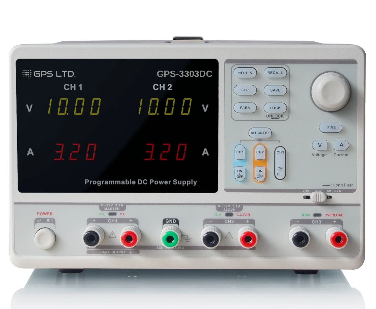
Three outputs, two that link
220 W in total. The two adjustable channels are independent until you press a key, at which point they become one supply of twice the voltage or twice the current.
| Mode | Voltage | Current | Set from |
|---|---|---|---|
| CH1 and CH2, independent | 0 to 32 V | 0 to 3.2 A each | Each channel |
| CH1 and CH2, series | 0 to 60 V | Up to 3.2 A | CH1, as master |
| CH1 and CH2, parallel | 0 to 32 V | Up to 6.4 A | CH1, as master |
| CH3 | 2.5 V, 3.3 V or 5 V | 3.2 A | A panel switch |
In series and in parallel the channels are linked internally and CH1 sets the pair. The front panel is marked with the terminals to use in each mode.
Setting it, and protecting what it feeds
Coarse and fine
A knob, and a button that slows it down
Coarse moves in 0.1 V or 0.1 A steps for getting there; fine drops to the full resolution of 10 mV and 10 mA for arriving. Setting and readback are both accurate to ±(0.5% of reading + 2 digits).
A switchable logic rail
2.5 V, 3.3 V or 5 V at 3.2 A
The third output is not a fixed 5 V supply. A panel switch selects 2.5 V, 3.3 V or 5 V, so modern logic levels are available without a regulator on the bench.
Over-current protection
A limit that opens, not one that holds
Separate from the constant current limit: set a protection value and the channel switches its output off when the current reaches it, rather than holding there. For a board you would rather disconnect than cook.
Series and parallel by button
No rewiring, no links
One key puts CH1 and CH2 in series for 60 V, another in parallel for 6.4 A. In both, CH1 becomes the master and sets the pair, and the front panel is silkscreened with which terminals to use.
Five stored setups
Mode, voltage and current together
Each memory holds the operating mode as well as the settings, so a recurring test is recalled in one action rather than rebuilt.
Key lock
A long press, or a command
Locks the front panel so a running test is not disturbed by a knock or a curious finger. Releases the same way, or over the interface.
In an automated rack
The USB port is not just for firmware. The instrument takes SCPI commands, so it can be driven and interrogated by a test script.
USB, class compliant
USBTMC, no driver hunt
The instrument enumerates as a test and measurement device, so it is visible to the usual instrument software without hunting for a driver.
SCPI command set
Channel, setting, measurement, output, mode
Select a channel, set or query voltage and current, read back what is actually being delivered, switch outputs, and change between independent, series and parallel, all remotely.
Status readback
What the instrument is really doing
A status query reports constant voltage or constant current per channel, the tracking mode, and which outputs are on, so a test script can check rather than assume.
Regulation and accuracy
| Constant voltage, line regulation | ≤ 0.01% + 3 mV |
|---|---|
| Constant voltage, load regulation | ≤ 0.01% + 3 mV |
| Constant voltage, ripple and noise | ≤ 1 mV rms, 5 Hz to 1 MHz |
| Constant current, line and load regulation | ≤ 0.2% + 3 mA |
| Constant current, ripple and noise | ≤ 3 mA rms |
| Series mode | Line ≤ 0.01% + 5 mV · load ≤ 300 mV |
| Parallel mode | Line and load ≤ 0.01% + 3 mV |
| CH3 | Line ≤ 0.01% + 3 mV · load ≤ 0.01% + 3 mV · ripple ≤ 1 mV rms |
| Tracking error | ≤ 0.5% + 10 mV of the master, no load |
| Recovery time | ≤ 50 µs for a fifty per cent load change, minimum load 0.5 A |
| Temperature coefficient | ≤ 300 ppm per °C |
Figures apply after about thirty minutes of warm-up at an ambient temperature between 20 °C and 30 °C.
Technical specifications
| Outputs | Three isolated channels · two adjustable 0 to 32 V at 0 to 3.2 A · one switchable 2.5 V, 3.3 V or 5 V at 3.2 A |
|---|---|
| Total power | 220 W |
| Operating modes | Independent, series and parallel, selected by key · constant voltage and constant current with automatic crossover |
| Resolution | 10 mV and 10 mA |
| Accuracy | Setting and readback both ±(0.5% of reading + 2 digits) |
| Display | Four-digit voltmeter to 32 V and three-digit ammeter to 3.2 A per adjustable channel, with mode indicators |
| Protection | Settable over-current protection per channel · short circuit and overload protection · CH3 overload indicator |
| Memory | Five setups, each holding mode, voltage and current |
| Interface | USB, class-compliant USBTMC, with a SCPI command set |
| Insulation | Case to terminal ≥ 20 MΩ · case to mains ≥ 30 MΩ, both at 500 V DC |
| Mains input | 100 V, 120 V, 220 V or 230 V ± 10%, 50/60 Hz, selected on a rear panel switch |
| Environment | Operating 0 °C to 40 °C below 80% RH · storage −10 °C to 70 °C below 70% RH · altitude to 2000 m · installation category II, pollution degree 2 |
| Size and mass | 275 × 225 × 136 mm · 7.5 kg |
| Warranty | 1 year, subject to product registration with GPS |
Before you order
It runs on any mains you have
100, 120, 220 or 230 V
A switch on the rear selects the input voltage, so the same instrument suits a UK bench, a European one or a North American one. Set it before connecting the lead, and note that the correct fuse rating changes with the setting.
The outputs float
None is tied to earth
CH1 and CH2 are isolated from the chassis and from each other, tested at 500 V DC, which is what allows one to be inverted for a negative rail. Bond a terminal to the ground post if your circuit needs a defined reference.
Series reaches 60 V
Treat the pair as one supply
In series the two channels are linked internally and the pair floats together. Earth at most one point of it, and switch the output off before changing any connection.
Standards
Confirmation on request
We will supply the declaration of conformity and the standards it cites with any quotation. Ask for it with your enquiry and we will send it before you order rather than after.
What’s in the kit
- GPS-3303DC power supply
- Mains lead
- USB cable
- Quick start guide
Available separately
Test leads, rack mounting and calibration are available from GPS. Control software is a free download. Tell us the quantity and we will quote the lot together.