
GPS-3004
GPS-3004 Four-Channel Linear DC Power Supply
Four channels · 0–32 V at 0–10 A each · 384 W across the instrument
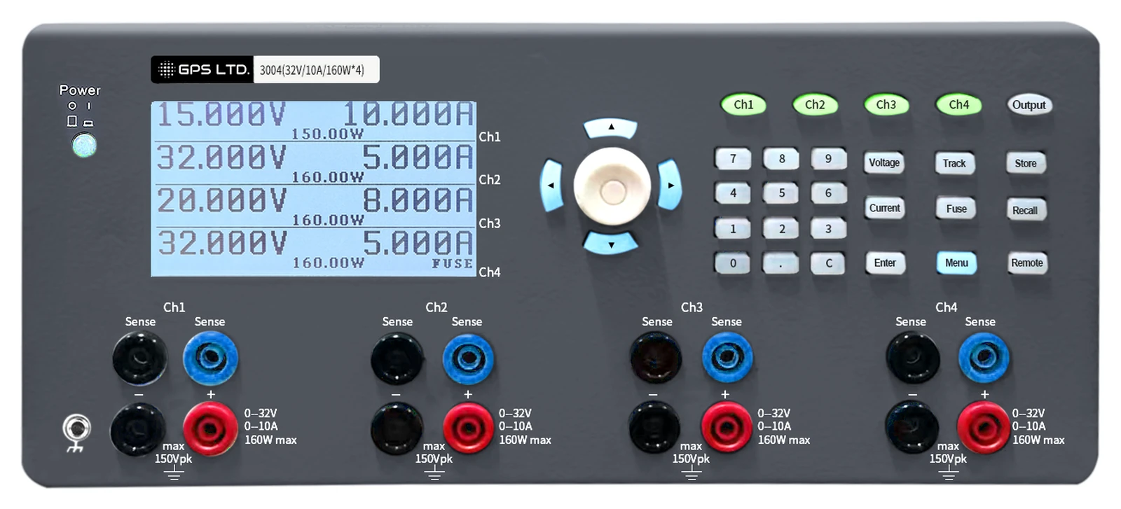
Four identical isolated channels, each 0 to 32 V at up to 10 A, sharing 384 W however you choose to divide it. Any channel suits any rail, they stack to 128 V or bundle to 40 A, and list sequencing and per-channel electronic fuses make it a supply for a test rig rather than only a bench.
384 W, distributed how you like
The four channels draw on one budget rather than four fixed allowances. Any channel will take up to 160 W in whatever combination of volts and amps suits the job, and how you spread the total across them is your decision, not the instrument’s.
Any shape you like, up to 160 W
The shaded area is what one channel will deliver: the full 10 A anywhere up to 16 V, and any voltage and current pairing on or inside the 160 W boundary above it.
384 W to allocate
Give it all to one demanding rail and three light ones, or spread it evenly across four. The instrument does not care how the budget is divided.
Some ways it divides
Multiply volts by amps for each rail and add them up. Anything to 384 W works, in any combination.
4 × 96 W is 384 W, within the 384 W budget.
4 × 160 W is 640 W, more than the 384 W budget.
2 × 160 W is 320 W, within the 384 W budget.
32 V × 8 A is 256 W, more than a channel’s 160 W.
| Item | Value | Notes |
|---|---|---|
| Channels | Four, identical | Every channel has the same range, so any of them will do for any rail |
| Per channel | 0 to 32 V at 0 to 10 A | Isolated and floating, so channels stack or invert freely |
| Channel power | Up to 160 W | In any voltage and current combination: 10 A anywhere to 16 V, 5 A at 32 V |
| Instrument power | 384 W | Shared across the four channels, divided however suits the job |
| Series | Up to 128 V | All four channels in series |
| Parallel | Up to 40 A | All four channels in parallel |
What it does besides hold a voltage
List sequence
A profile, not a procedure
Steps through programmed voltage and current values on its own, so a power-up order is run by the instrument rather than followed by hand and got wrong occasionally.
Synchronous output
Move one, move all
Change a parameter on one channel and the corresponding parameter on the others changes in proportion. Useful on a board whose rails are related rather than independent.
Battery charging curve
Simulated, not approximated
A charging profile can be reproduced, so a charger under test sees something like a cell rather than a fixed source that never sags.
Electronic fuses
A delay you can set
Configured independently per channel, responding in under 10 ms, with a delay settable from 0 to 250 ms in 10 ms steps. Long enough to let an inrush through, short enough to catch a fault. Fuses can be linked, so a trip on one rail switches off the others that feed the same board.
Soft limits
The knob cannot go past what you allow
A voltage and a current limit set per channel cap the adjustment range itself. Set them to what the board tolerates and the wrong value cannot be entered, which on four rails is the simplest protection there is.
Warning bands
A rail drifting, not failing
An upper and lower figure per channel on both voltage and current. Leave the band and the display flags it, without switching anything off. For spotting the rail that is wandering before it becomes a fault.
Over voltage protection
Measured, or as set
Per channel, preset to 32.5 V, and referenced either to the voltage actually at the terminals or to the value you set. The output closes when it is exceeded.
Remote sensing
Regulate at the load
Compensates up to 1 V of drop along the load leads, which at 10 A is the difference between the voltage you set and the voltage the board sees.
Front and rear terminals
Use the back at high current
Output is available at both ends. The rear connection has the lower resistance and is the one to use when a channel is working hard.
In an automated rack
Four rails, a list sequence and a remote interface are most of what an automated bench needs from a supply.
RS-232 and USB
Both fitted as standard
No adapter and no option to specify: the instrument arrives able to talk to a bench PC or a rack controller, at 4800 to 115200 baud.
SCPI or MODBUS
Whichever your system speaks
The command set is selectable, so the supply drops into a test framework or into industrial control without a translator in between.
LAN, if you need it
Fitted during manufacture only
It cannot be added afterwards, so an instrument that may end up on a network needs the option specified at the time of order rather than when the need arises.
Quick to answer
Command handling under 50 ms
Fast enough that a test script stepping four channels is not waiting on the supply between steps.
Regulation and accuracy
| Setting accuracy, voltage | ≤ 0.05% + 5 mV at 25 °C ± 5 °C |
|---|---|
| Setting accuracy, current | ≤ 0.1% + 5 mA at 25 °C ± 5 °C |
| Readback accuracy, voltage | ≤ 0.05% + 5 mV |
| Readback accuracy, current | ≤ 0.1% + 2 mA |
| Resolution, voltage | 1 mV, setting and readback |
| Resolution, current | 0.2 mA below 1 A · 1 mA at and above |
| Line regulation | Voltage ≤ 0.01% + 2 mV · current ≤ 0.01% + 250 µA |
| Load regulation | Voltage ≤ 0.01% + 2 mV · current ≤ 0.01% + 250 µA |
| Ripple and noise | Voltage ≤ 1.5 mV rms · current ≤ 1 mA rms, 20 Hz to 20 MHz |
| Electronic fuse | Response < 10 ms · delay 0 to 250 ms in 10 ms steps, per channel |
| Remote sensing | Compensates up to 1 V of lead drop |
Figures apply after about thirty minutes of warm-up at an ambient temperature between 20 °C and 30 °C.
Technical specifications
| Outputs | Four identical channels, 0 to 32 V at 0 to 10 A, isolated and ungrounded |
|---|---|
| Power | 160 W per channel · 384 W across the instrument |
| Series and parallel | Up to 128 V in series · up to 40 A in parallel |
| Operating modes | Constant voltage and constant current · list sequence · synchronous output · battery charging curve |
| Protection | Over voltage protection per channel, preset 32.5 V, referenced to the measured or the set voltage · over current and over temperature · overload and short circuit on every channel · electronic fuses with settable delay and linking |
| Limits and warnings | A voltage and a current soft limit per channel, capping the adjustment range · and a warning band on each, flagged on the display when the output leaves it |
| Memory | Ten instrument setups · three arbitrary waveforms per channel · the power-on output state is set in the menu |
| Interfaces | RS-232 and USB fitted, with cables for both supplied · LAN fitted during manufacture only · SCPI or MODBUS at 4800 to 115200 baud · command handling under 50 ms |
| Mains input | 110 V or 220 V ± 10% |
| Environment | Operating 5 °C to 40 °C below 80% RH · storage −20 °C to 70 °C below 80% RH |
| Size and mass | 285 × 136 × 405 mm · 14.0 kg |
| Warranty | 1 year, subject to product registration with GPS |
| Part number | 523004 |
Before you order
Size your rails against 384 W
Not against four times 160 W
The budget is shared, so add your rails up before ordering. If the total goes over, the instrument switches its output off and tells you, which is better than finding out through a brown-out but is worth avoiding altogether.
The outputs float
None is tied to earth
All four channels are isolated from the chassis and from each other, which is what allows them to be stacked to 128 V or inverted for a negative rail. Bond a terminal to the ground post if your circuit needs a defined reference.
Standards
Confirmation on request
We will supply the declaration of conformity and the standards it cites with any quotation. Ask for it with your enquiry and we will send it before you order rather than after.
What’s in the kit
- GPS-3004 power supply
- Mains lead
- USB cable
- RS-232 cable
- Sense leads
- Test leads, four
- User manual
Available separately
The LAN interface is fitted during manufacture and cannot be added afterwards, so it has to be specified with the order. Rack mounting and calibration are available from GPS. Tell us the quantity and we will quote the lot together.