
GPS-8512C
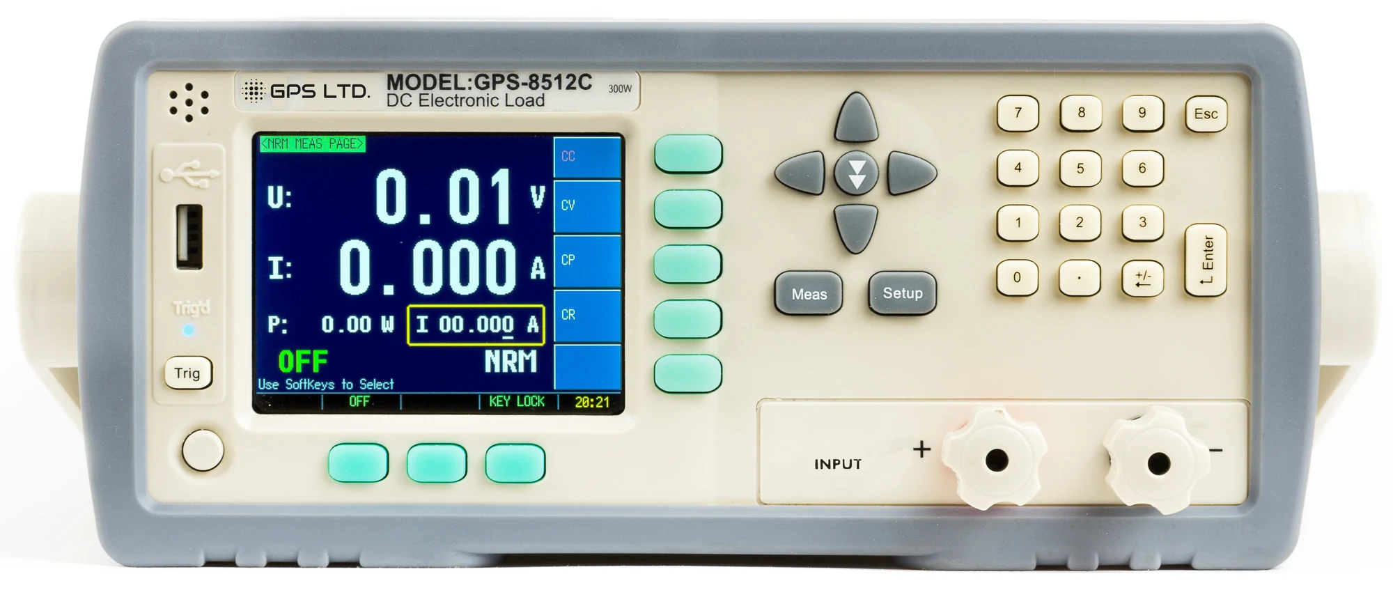
GPS-8512C Programmable DC Electronic Load
300 W · 300 V · 30 A · CC / CV / CP / CR
A bench load for proving power supplies, chargers and batteries. Constant current, voltage, power and resistance modes run on their own or chained into sequences, so a supply is loaded the way it will actually be used rather than through a bank of resistors.
What it can take
Three headline figures that describe a region rather than a point. The shaded area is everything the instrument will sink: the full 30 A up to 10 V, and the 300 W boundary above it.
Will it take your source?
Multiply the voltage by the current you want to draw and compare with 300 W. Four worked examples:
A 12 V supply at full 20 A load
Within the envelope
12 V × 20 A is 240 W, inside 300 W.
A 48 V telecoms rail at 5 A
Within the envelope
48 V × 5 A is 240 W, inside 300 W.
A 24 V supply at 15 A
Outside the envelope
24 V × 15 A is 360 W, over the 300 W limit.
A 300 V source at 1 A
Within the envelope
300 V × 1 A is 300 W, inside 300 W.
The curve and every verdict are generated from the rated power, voltage and current, so they cannot disagree with the figures in the table below.
Four ways to load a source
The modes are a choice rather than a feature list. The rule of thumb is to load a constant-voltage source with constant current, and a constant-current source with constant voltage.
Constant current
CC · for a constant-voltage source
The load draws a set current whatever the voltage does. Set the current you want a supply, a charger output or a rail to deliver, and watch what its voltage does.
Constant voltage
CV · for a constant-current source
The load draws whatever current holds its terminals at a set voltage. This is the mode where constant current would fight the source, and it is also how an LED driver is simulated.
Constant power
CP · as a real load behaves
The load holds the product of voltage and current. As the source sags it draws more current to compensate, which is what a switching load actually does and what a battery sees in service.
Constant resistance
CR · as a passive load
The load behaves as a fixed resistance, current rising with voltage, for a device under test that expects a passive load rather than an active one.
What it runs on its own
Most of what a load is for happens after you walk away from it.
Transient
Two levels with independent timing, 0.1 Hz to 1 kHz, run continuously, as single pulses or on a trigger. How a supply’s response to a step load gets measured rather than guessed at.
Sequence
Ten files of up to a hundred steps, each with its own level and a duration from 0.01 s to 60 s, looped or triggered. A profile once entered is a profile for good.
Automatic test
Ten files of twenty steps, each step constant current, voltage, power or resistance, or short, or open, with upper and lower limits. The instrument returns a pass or a fail.
Battery discharge
Constant current to a set cut-off voltage, reporting capacity to 999.99 Ah and elapsed time to 1000 hours, so a cell is characterised rather than merely flattened.
Driven from a PC
A built-in RS-232C port with a SCPI command set, baud rate to 115200, and data acquisition software supplied. RS-485 is available as an option for putting several instruments on one bus.
Triggered from the rig
An external trigger input on the rear panel, with internal, bus and external trigger modes, so a sequence or a transient step ties to whatever else the rig is doing.
Ranges and accuracy
| Mode | Range | Resolution | Accuracy |
|---|---|---|---|
| Constant current | 0 to 3 A | 0.1 mA | ±(0.1% + 0.1% FS) |
| Constant current | 0 to 30 A | 1 mA | ±(0.2% + 0.1% FS) |
| Constant voltage | 0 to 18 V | 1 mV | ±(0.05% + 0.02% FS) |
| Constant voltage | 0 to 150 V | 10 mV | ±(0.05% + 0.025% FS) |
| Constant power | 0 to 100 W | 1 mW | ±(1% + 0.1% FS) |
| Constant power | 100 to 300 W | 10 mW | ±(1% + 0.1% FS) |
| Constant resistance | 0.1 to 99 Ω | 0.01 Ω | ±(1% + 0.3% FS) |
| Constant resistance | 100 Ω to 4 kΩ | 0.1 Ω | ±(1% + 0.8% FS) |
| Monitor | Voltage and current | 1 mV and 0.1 mA | 0.05% and 0.1% |
Accuracy is ±(% of setting + % of full scale) at 23 ± 5 °C, after a short-circuit zero and more than sixty minutes of warm-up, within twelve months of adjustment. Full scale is that of the range in use.
Technical specifications
| Input rating | 300 W · 300 V · 30 A · derated at low voltage along the 300 W boundary |
|---|---|
| Load modes | Constant current, constant voltage, constant power and constant resistance, selected by soft key |
| Test functions | Normal, transient, sequence, automatic test, battery, LED load, over-current, over-power and short circuit |
| Sequence and automatic test | Ten sequence files of up to a hundred steps · ten automatic test files of twenty steps · step timing 0.01 s to 60 s |
| Battery test | Constant current discharge to a cut-off voltage · capacity to 999.99 Ah · elapsed time to 1000 hours |
| Short circuit test | About 30 A at about 40 mΩ |
| Sampling rate | Three rates: three, five or ten readings a second |
| Display | 3.5 inch true colour TFT showing voltage, current, power, resistance, battery capacity and discharge time |
| Sensing | Four-wire remote sensing on the rear panel, switched on in the setup page |
| Interface | RS-232C built in with a SCPI command set · baud rate to 115200 · RS-485 available as an option · external trigger input |
| Protection | Over voltage, over current, over power, reverse polarity and over temperature · the input opens on trip |
| Power | 198 to 252 V AC · 48.5 to 52.5 Hz · 15 VA maximum |
| Environment | Operating 10 °C to 40 °C at 10 to 80% relative humidity |
| Size and mass | 264 × 107 × 350 mm · 5.0 kg net |
| Warranty | 1 year, subject to product registration with GPS |
Protection and connection
What the instrument does to look after itself and the source, and the handful of things worth knowing before the first connection.
Five trips on the input
Over voltage, current, power, polarity and heat
Any of the five opens the input rather than warning and carrying on, so a wrongly connected source is disconnected rather than tolerated.
Four wires, not two
Remote sensing on the rear panel
At 30 A the drop along the load leads is not a rounding error. Sense terminals take the voltage reading at the source instead, and four-wire mode is switched on in the setup page.
The short circuit test is the exception
Over-current protection is off
Protection is disabled during the short circuit test, which is the point of the test. Worth knowing before you run it, and worth checking the source survives about 30 A into about 40 mΩ.
Constant voltage is specified to 150 V
Against a 300 V input rating
The input is rated to 300 V and the envelope is drawn to it, but the constant voltage setting range is specified to 150 V. If your work needs constant voltage above that, ask us before ordering.
A single mains range
198 to 252 V at 48.5 to 52.5 Hz
Drawing 15 VA at most. There is no voltage selector to set, so there is nothing to get wrong on the first power-up.
Derating at low voltage
Full current below 10 V
Below 10 V the whole 30 A is available; above it the 300 W boundary governs. The chart near the top of this page draws all of it.
What’s in the kit
- GPS-8512C electronic load
- Test lead set
- AC power cord and RS-232 communication cable
- Data acquisition software
- User manual
Available separately
The RS-485 interface is an option specified with the order rather than fitted afterwards. Rack mounting, spare fuses and calibration are available from GPS.