
DC Electronic Loads
Test a supply the way its load will
An electronic load draws what you tell it to and holds that setting while the supply under test does whatever it does. Constant current, voltage, power or resistance, measured as it runs, sequenced if you need it, and protected against the mistakes a bank of resistors will not save you from.
The load
300 W across 0 to 300 V and 0 to 30 A, in four modes, with a sequencer and a remote interface.
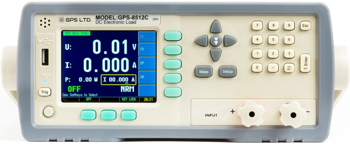
GPS-8512C
Programmable DC Electronic Load
0 to 300 V and 0 to 30 A within a 300 W envelope, in constant current, voltage, power or resistance. A 3.5 inch colour display, list sequences of up to 100 steps a file, battery testing to 1000 hours, and RS-232C and USB for remote control.
Four things a box of resistors will not do
A resistor is cheap and it will dissipate power. What it will not do is hold a setting, change on command, tell you what it saw, or look after itself.
It holds its setting while the supply moves
A resistor draws whatever Ohm’s law gives it. If the supply sags under load, the current falls with it and you are no longer testing what you set out to test. An electronic load in constant current mode holds the current and lets the voltage do what it likes, which is what makes the result mean something.
It changes without a soldering iron
Sweeping a supply from no load to full load with resistors means a box of them and a lot of swapping. Here it is a number you type, and a sequence of numbers if you want the whole curve.
It measures while it loads
Voltage, current and power are read at the terminals as the test runs, so the supply’s regulation and its droop are visible without a meter clipped across it.
It protects itself, and your supply
Over voltage, over current, over power and over temperature are all watched, and the fan is sized for continuous dissipation. A wirewound resistor at 300 W does none of that and gets hot enough to matter.
Four modes, and when each one is right
The mode decides what the load holds constant while everything else moves. Picking the wrong one is the commonest way to get an answer that looks fine and means nothing.
Constant current CC
Draws the current you set whatever the voltage does. The mode for testing a supply’s regulation, its current limit and how it behaves at the crossover point.
Constant voltage CV
Holds its own terminal voltage and sinks whatever current arrives. The mode for testing a charger or any source that is itself trying to control current.
Constant power CP
Draws the power you set, taking more current as the voltage falls. This is how a real device behaves, which makes it the mode for battery discharge and runtime work.
Constant resistance CR
Behaves as a fixed resistance, down to 0.1 Ω. The mode for simulating a resistive load and for watching how a supply starts up into one.
Four things worth settling first
Check all three numbers, not one
A load is bounded by voltage, by current and by power together. The GPS-8512C reaches 30 A and it reaches 300 V, but not at the same time: 300 W is the envelope, so the full 30 A is available to 10 V and at 300 V the load will take 1 A. Multiply your supply’s voltage by the current you want to draw and check that figure first.
Which mode does your test want?
Testing a power supply usually means constant current. Testing a charger usually means constant voltage. Battery runtime means constant power, because that is what the device on the end of the battery actually does. Constant resistance is for simulating a passive load.
Mind the minimum voltage
An electronic load is a controlled transistor, and it needs a volt or so across it to control anything. Drawing heavy current from a very low voltage rail is the one thing loads of this class find hard, so check the minimum operating voltage against your lowest rail.
Think about where the heat goes
300 W is a fan heater on a bench. The instrument handles its own dissipation, but the room has to take it, and a rack needs the airflow planned rather than assumed.