Handheld Multimeter · Electrical Test
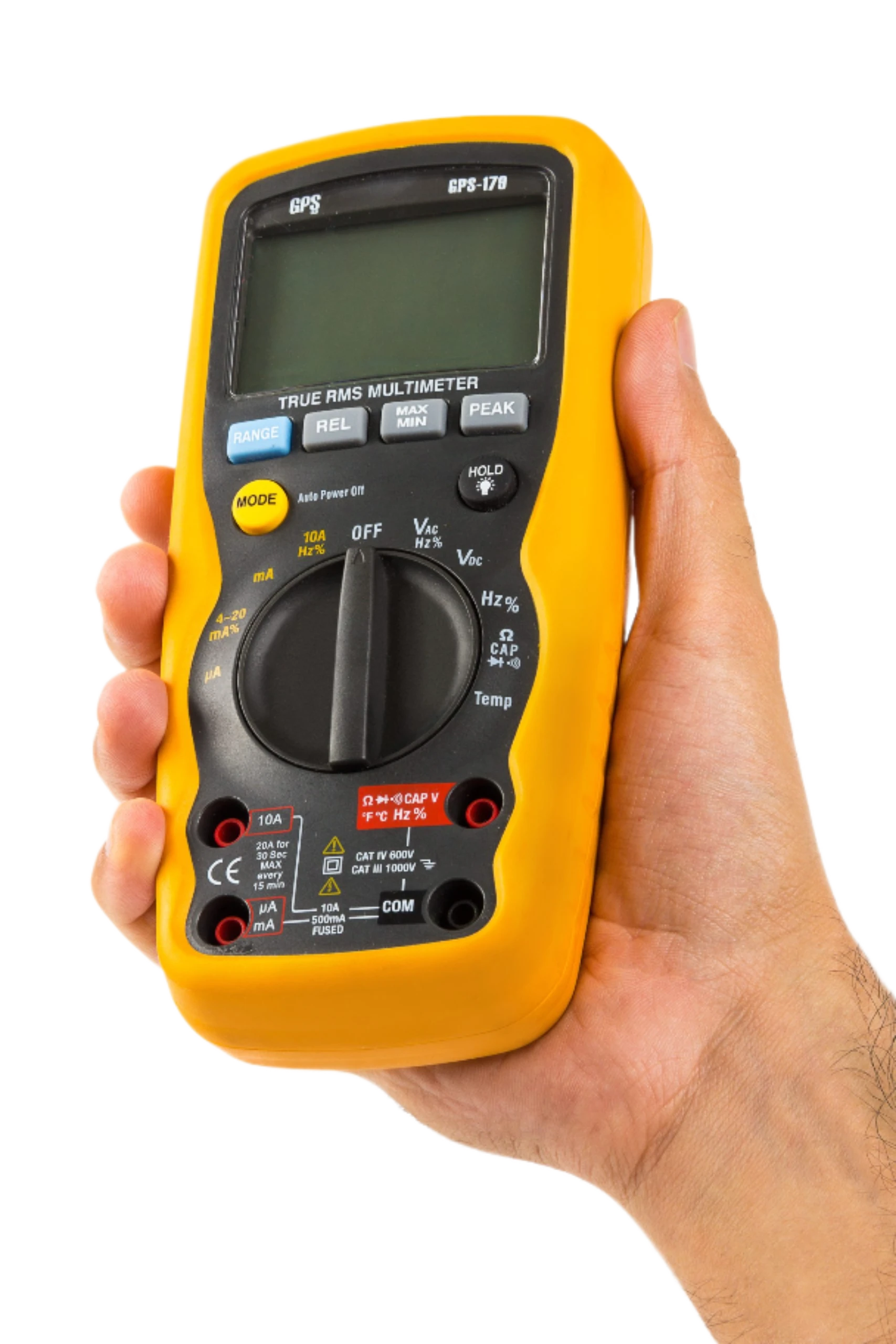
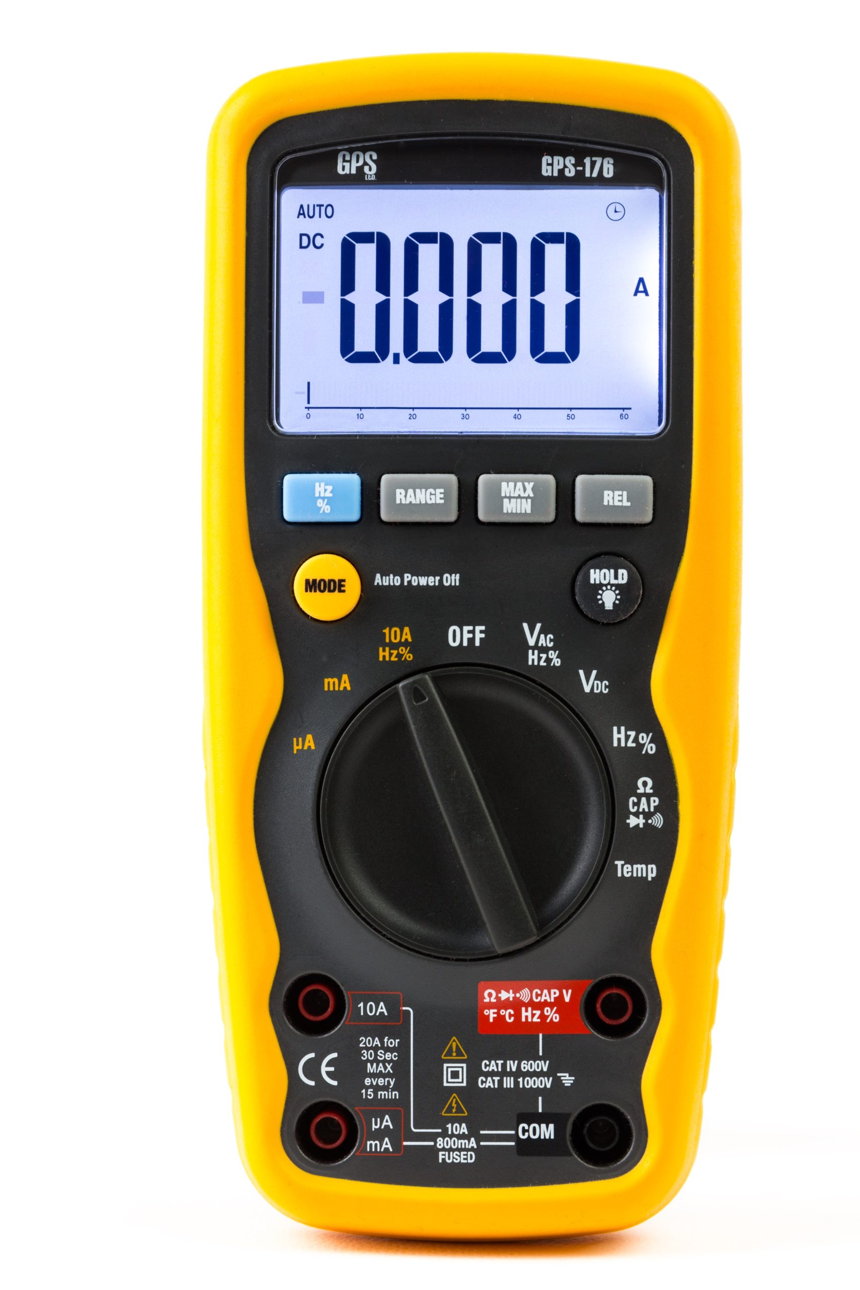
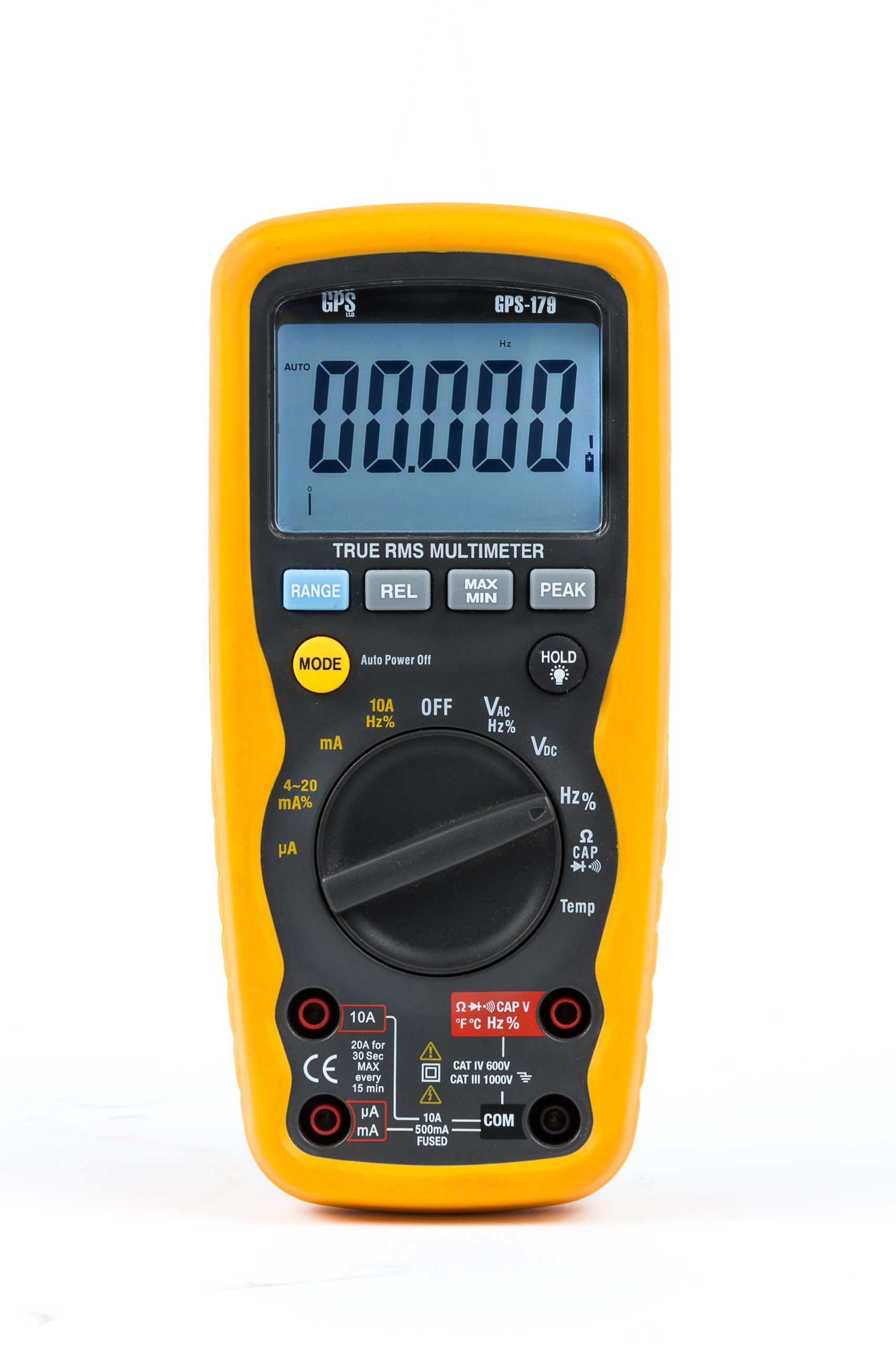
GPS‑176 / GPS‑179
Rugged, IP67 handheld multimeters with large backlit display, auto‑ranging and
CAT IV 600 V / CAT III 1000 V safety rating. The GPS‑179 adds True‑RMS and
4–20 mA process loop % measurement for industrial commissioning and maintenance.
GPS‑179: 40,000 counts · True‑RMS
GPS‑176: 6,000 counts
IP67 dust/water resistant
Backlit LCD · Bar graph
1000 V protection on all ranges
Max/Min · Data Hold
Type‑K temp to 760 °C
Diode & continuity
Key features
Rugged IP67
Dust & water resistant enclosure for harsh environments.
Safety first
CAT IV 600 V / CAT III 1000 V; 1000 V protection on all ranges.
High‑visibility display
Backlit LCD with bar graph; 40,000 counts (179) / 6,000 counts (176).
Industrial functions
4–20 mA loop % (179), temperature (K‑type) to 760 °C, duty, frequency.
Where it excels
Field maintenance
Outdoor electrical checks, PV & wind systems, plant utilities.
Industrial commissioning
4–20 mA loop verification (179), PLC & drive panels, control cabinets.
Education & labs
Robust meters for teaching labs and general R&D benches.
Automotive & EV
Low‑voltage diagnostics with fast Min/Max capture and continuity.
Models & key specifications
| Model | Display | Measurement highlights | Capabilities |
|---|---|---|---|
| GPS-179 | 40,000 counts · Bar graph · Backlit |
|
True-RMS, 4–20 mA loop %, Min/Max, Relative, Peak, Data Hold |
| GPS-176 | 6,000 counts · Bar graph · Backlit |
|
Min/Max, Relative, Data Hold |
See datasheet for full ranges, resolutions and accuracy conditions; GPS-170 model is discontinued and not offered.
Safety & Compliance
Safety: EN 61010‑1; CAT IV 600 V / CAT III 1000 V rating, with
1000 V protection on all ranges. Fused 10 A / 1000 V and 0.5–0.8 A / 1000 V (model‑dependent).
Downloads & resources
Datasheet (PDF)
Reference diagram — 4–20 mA loop verification (GPS-179)
Series measurement (mA / % loop)
- Power down the loop. Break the loop between the transmitter “− LOOP” and PLC “+ IN”.
- Connect GPS-179 in series: mA INPUT to transmitter “−”, and COM to PLC “+ IN”.
- Power up. Set meter to mA (or 4–20 mA %). Verify reading is within expected span.
- Apply a known process value or use transmitter’s simulation to confirm 4 mA (0 %), 12 mA (50 %), 20 mA (100 %).
Safety: Observe loop voltage/current limits and the meter’s fuse rating. Use correct jacks (mA/COM) and confirm polarity.
Reference diagram — Loop power supply test (GPS-179)
Verify loop supply current delivery (series test)
- Power down the loop supply. Prepare a dummy load: use 1.2 kΩ to simulate 20 mA, or 6 kΩ for 4 mA at ~24 V (R≈V/I).
- Wire GPS-179 in series: mA INPUT to the supply “+”, COM to the dummy load, then load back to supply “−”.
- Power up. Set the meter to mA (or 4–20 mA %). Confirm ~4.00 mA or 20.00 mA is delivered.
- (Optional) Swap in actual loop burden (e.g., PLC analog input) to verify compliance under real load.
Safety & tips: Observe resistor wattage (P=I²R → at 20 mA & 1.2 kΩ, ~0.48 W; use ≥1 W for margin).
Always use the correct mA jack and confirm the meter’s fuse rating.
Ready to evaluate this instrument?
Request a quote