
GPS-8055C
GPS-8055C Dual Display Multimeter
240 000 count dual display · true RMS · two-wire and four-wire resistance
Five and a half digits at the slow rate, where the accuracy figures are specified, and 150 readings a second at four and a half when throughput matters more than the last digit.
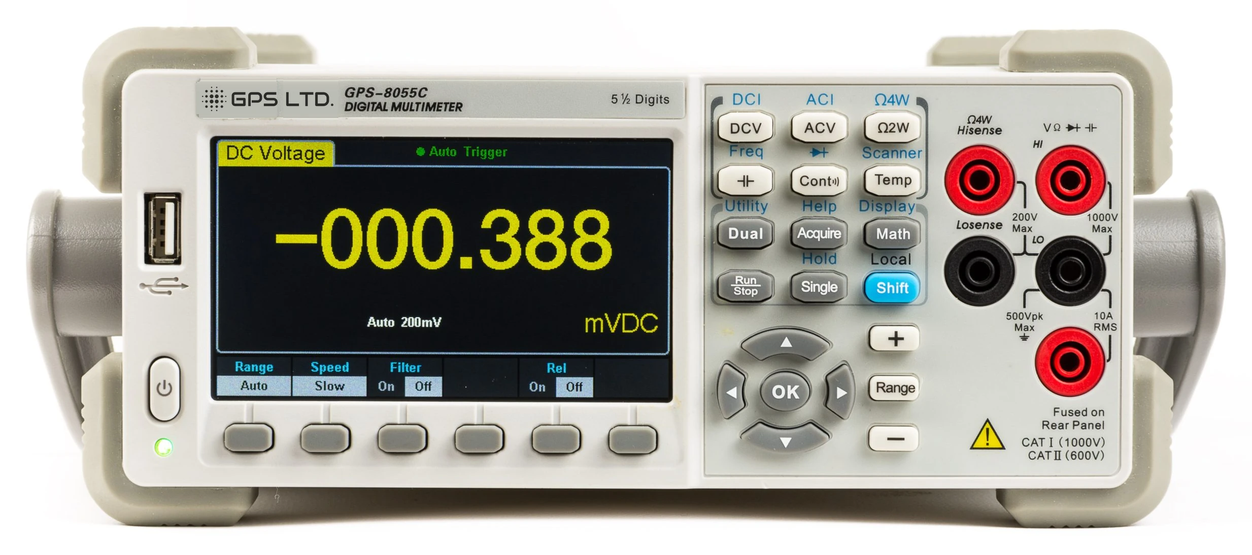
What the fifth digit is for
Any instrument can show more digits. Whether the last one means anything comes down to three things, and all three are settings or connections rather than claims.
The count, and the rate that earns it
240 000 counts across the range, which puts 1 µV steps on the 200 mV range and 1 mΩ on the 200 Ω range. That resolution belongs to the slow rate, five readings a second, and every accuracy figure quoted anywhere on this page is specified there.
Four wires, so the leads stay out of the answer
Below an ohm or so the leads and the contacts contribute more than the part does, and no amount of resolution fixes that. Two terminals drive the current and two sense the voltage, so the reading is taken at the part rather than at the end of a cable. The same seven ranges either way.
Ten gigohms, so the meter stops loading the circuit
On the 200 mV and 2 V ranges the DC input impedance lifts from 10 MΩ to above 10 GΩ. On a high impedance source that is the difference between measuring a voltage and changing it, and here it is a setting rather than a second instrument.
- 240 000 counts · 1 µV on the 200 mV range
- ±(0.015% + 0.003) basic DC accuracy over a year
- Two-wire or four-wire, 200 Ω to 100 MΩ
- 10 MΩ or above 10 GΩ DC input impedance
- True RMS on AC voltage and AC current
- Five readings a second at the full 5½ digits
The two faster reading rates trade the fifth digit for throughput. Wherever a rate appears on this page the digits that go with it appear beside it.
Every function, every range, one screen
Scan down for the function, across for the range. Where a row is all dashes the instrument does not do it, so the table reads the same way on every meter in this category.
| Function | Lowest | Highest | Best resolution | Basic accuracy | Notes |
|---|---|---|---|---|---|
| DC voltage | 200 mV | 1000 V | 1 µV | ±(0.015% + 0.003) | Five ranges · 10 MΩ, or above 10 GΩ on 200 mV and 2 V |
| AC voltage | 200 mV | 750 V | 1 µV | ±(0.2% + 0.05) | True RMS · 20 Hz to 100 kHz · figure is 45 Hz to 20 kHz |
| DC current | 200 µA | 10 A | 1 nA | ±(0.055% + 0.005) | Six ranges · above 7 A, thirty seconds on and thirty off |
| AC current | 20 mA | 10 A | 100 nA | ±(0.50% + 0.10) | True RMS · figure is 45 Hz to 2 kHz on 20 mA and 200 mA |
| Resistance | 200 Ω | 100 MΩ | 1 mΩ | ±(0.020% + 0.003) | Seven ranges · two-wire or four-wire · under 8 V open circuit |
| Capacitance | 2 nF | 10 000 µF | — | ±(1% + 0.5) | Six ranges · ±(3% + 1.0) on the 2 nF range |
| Frequency | 20 Hz | 1 MHz | — | ±(0.01% + 0.003) | Measured on the 200 mV to 750 V AC ranges · figure below 200 kHz |
| Frequency, high | — | — | — | — | Not a function of this instrument |
| Period | 1 µs | 0.05 s | — | ±(0.01% + 0.003) | Same input ranges as frequency |
| Temperature, RTD | −200 °C | 660 °C | — | 0.16 °C | Platinum, α = 0.00385 · four-wire, or two-wire with REL |
| Temperature, thermocouple | −270 °C | 1820 °C | — | 0.5 °C | Eight types · built-in cold junction, ±2 °C |
| dBm | — | — | — | — | Computed from the voltage reading · reference impedance settable from 50 Ω to 8000 Ω |
| Continuity | — | 2 kΩ | — | ±(0.05% + 0.01) | Fixed range · 1 mA test current · threshold 0 to 2000 Ω |
| Diode | — | 2 V | — | ±(0.05% + 0.01) | 1 mA test current · beeper from 0.1 V to 2.0 V |
| Rotation speed | — | — | — | — | Not a function of this instrument |
| Square wave out | — | — | — | — | Not a function of this instrument |
Accuracy is specified for one year after calibration, at 23 ± 5 °C, after thirty minutes of warm-up and at the slow reading rate, in the form ±(% of reading + % of range). Each figure is the best available across that function’s ranges, so it does not hold on every range; range-by-range figures are in the datasheet. Resolution is quoted at 5½ digits, where the display count fixes it.
What it does with the readings
Between taking a reading and knowing something there is usually a notebook. Most of what would go in it is already on the instrument.
Two readings, one probe placement
The second display pairs with the first rather than repeating it: DC volts with DC current, AC volts with frequency or period, resistance with capacitance. On a four-terminal measurement that saves unclipping and re-clipping the part to get the other number.
Four ways to look at the same number
Number, bar meter, trend chart and histogram. The trend chart shows drift across a long run with nothing attached to the instrument. The histogram shows the spread of a batch, which is the difference between knowing a part passed and knowing how close it came.
Statistics that accumulate as it runs
Maximum, minimum, average, span and standard deviation build up over the run. dBm and dB work against a reference impedance set anywhere from 50 Ω to 8000 Ω, and a relative reading subtracts a stored offset, which is how lead resistance comes out of a two-wire measurement when four-wire is not practical.
A verdict, not just a number
Upper and lower limits put a high, in or low result on the display with a beeper behind it, so a batch can be sorted at the bench without anyone reading the digits. That is useful long before a job is worth automating.
Putting it on the network
The same instrument, driven rather than read. It drops into an existing test sequence rather than needing one written around it, and nothing below is an option except the GPIB adapter.
Control
- USB device, USB host and 10/100 LAN, all standard
- SCPI, compatible with mainstream multimeter command sets
- EasyDMM supplied for logging from a PC
- USB to GPIB adapter available for benches already on GPIB
Inside a sequence
- Automatic, single and external trigger
- 1 to 10 000 samples a trigger
- Trigger delay from 6 ms to 10 000 ms
- Voltmeter complete output on the rear panel
- 10 000 readings held while the instrument is powered
- Settings and data as XML or CSV, to flash or a USB drive
The voltmeter complete output tells the rest of the rig that a reading is ready, rather than leaving it to a fixed wait long enough to be safe.
Before you order
Three things that are easier to know now than after the instrument arrives. None of them is unusual for a meter of this kind; all three are easier to find here than on a specification sheet.
Digits or speed, not both
Three reading rates, and they are not the same instrument. The slow rate reads five times a second at the full 5½ digits, and every accuracy figure on this page is specified there. The two faster rates run at 4½ digits, up to 150 readings a second, which is what a production line wants and not what a reference measurement wants.
The top ranges are CAT I work
The panel is marked CAT I 1000 V and CAT II 600 V, which are two permissions rather than one range: up to 1000 V on circuits isolated from the mains, but 600 V once the leads are on a mains-connected circuit. The 750 V AC and 1000 V DC ranges are therefore CAT I only.
There is no universal input
A selector on the rear panel sets the instrument to 110 V or 220 V. A unit shipped to the UK should already be on 220, but it is worth confirming before the first power-up rather than after. Consumption is 20 VA maximum.
The terminal block is marked 1000 V max, 500 Vpk max to earth and 10 A rms, fused on the rear panel.
What’s in the box
- GPS-8055C meter
- Test lead set with alligator clips
- USB cable and AC power cord
- Spare current fuse
- Quick start guide
- EasyDMM software
What is not in the box
A USB to GPIB adapter, which is the only accessory most benches add and only then if the rig is already on a GPIB bus. Everything on the matrix works with what is supplied. Test leads, fuses and calibration are available from GPS, and a certificate can be issued with the order rather than afterwards.